Miscellaneous
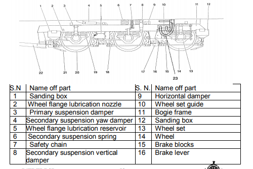
Mechanical features of 3-phase AC loco. The three axles, three motor Co-Co bogie assemblies, is one of the major parts of the Locomotive. Two bogie assemblies support the entire weight of the 3-phase locomotive and provide a means for transmission of the tractive effort to the rails. The bogies are designed to withstand the stresses and vibrations resulting from normal rolling stock applications. An important function of the bogie is to absorb and isolate shock caused by variations in the track bed. The suspension systems minimize the transmission of these shocks to the locomotive under frame. The traction motors are suspended in the bogie frame and on the individual axles. The motors transmit their energy to the driving axles through a gearbox mounted on the driving axle. The force from the driving axles is transmitted to the contact point between the wheel tread and the rail. Traction force is, in turn, transmitted through the axle journal boxes and guide rods to the bogie frame. The push-pull link rod, connected between the bogie transom and loco under frame, transmits the tractive forces to the loco body.
As with the tractive effort, braking effort is transmitted to the bogie frame by the axle journal boxes and guide rods and from the bogie frame to the locomotive by the traction rods.
Isolation and absorption of shock loads and vibration is performed by the primary and secondary suspension. Movement between the loco body and bogie is smoothly controlled by the primary and secondary suspension. Although the springs permit free movement in any direction, lateral buffers and dampers limit the amount and rate of lateral movement. Rebound limit chains and vertical dampers limit the amount the rate of vertical rebound of the locomotive loco body.
Yaw (longitudinal) dampers control the loco body pitch rate. Guide rods control the fore and aft movement between the axles and the bogie frame, while the link rod controls the fore and aft movement between the bogies and the loco body.
Primary suspension, located between the axles and the bogie frame, is provided by twin coil springs on the axle journal box fore and aft of the axle line. Vertical hydraulic dampers are used to dampen the rebound rate of the springs.This “Flexicoil” arrangement permits lateral movement of the axle. Longitudinal control of the axle, and the transmission of tractive and braking effort to the bogie frame, is provided by guide rods connected between the axle journal boxes and bogie frame. Spheribloc rubber bushes in the guide rods allow the axle lateral movement without undue restriction.
Secondary suspension is also provided by coil springs and vertical hydraulic dampers located between the bogie frame and the locomotive under frame on each side of the bogie. The weight of the loco body is carried by the secondary suspension springs.The“Flexi Float” arrangement of the secondary suspension allows the loco body to move both laterally and vertically within certain limits relative to the bogies.
Bogie layout