2. ICF COACHES
Introduction
An attempt for standardization of manufacturing of passenger coaches led to development of IRS design of steel body coaches. In 1954 Steel body coach design was taken from M/S Schlieren Switzerland for manufacturing of ICF Coaches at Perambur.
Initially original speed of ICF coach was 96 kmph since secondary suspension was laminated spring. The design was modified to all coil bogies with longer suspension hanger and weight transfer through side bearers, thereby enabling speed potential to 105 kmph on mainline coaches and gradually enhanced to 140 kmph for Shatabdi, Rajadhani and Janshatabdi coaches as per RDSO report No CWI Vol 1.
Initial coaches manufactured were with Vacuum brake and later modified into twin pipe graduated release air brake system – under frame mounted. Due to frequent failure of SAB and heavy vibrations of pull rod this was further modified into Bogie Mounted Brake System. Brake rigging pins were reduced from 104 Nos to 82 Nos.
Drawbar capacity is enhanced from 36t to 75t.
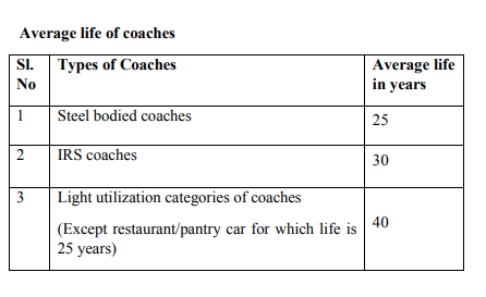
The codal life of ICF coaches of normal utilisation coaches is 25 years and light utilisation coaches are 40 years.
Dimensions of Coach
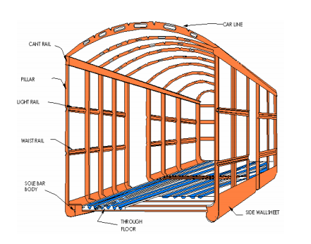
2.1 ICF COACH SHELL / BODY
Construction of coach body which forms big tubular hollow construction which is light in weight.
2.1.1 Salient Features of ICF Coach Shell / Body
All Metal: – ICF coach shell is made up of steel channel frames of thin sections except the seats & luggage racks which are made up of wooden members.
Light Weight:-The weight of coach shell is reduced due to minimal use of wooden members, use of anti-corrosive Corten Steel (IRSM 41) of thickness 1.6 mm for roof and 2 mm thickness for corrugated floor, side panel and end panels during fabrication of coach body. The use of gusset plate, knee & rivets are also avoided in under frame. Hence weight of ICF shell is reduced by 26% to 32% compared to IRS coach shell which was used in the past.
Integral Construction:-The shell of ICF coach is formed by welding together body side pillars, roof carlines, waist rail, light rail, cant rail & sole bar. Corrugated flooring, side panels, end panels & roof are welded together by means of homogenous welding. End pillars, stanchions and side pillars are also connected with panelling work. This type of structure gives the integral
Anti-telescopic construction:-The shell of ICF Coach is designed to bear 45 tons of vertical load and 200 tons of longitudinal impact on side buffers. The coach body is so designed that it is stronger at end portion as well as in passenger seating portion and less at the doorway and toilet. Due to which maximum kinetic energy during accident is absorbed by the end portion and get damaged and balance kinetic energy is also shared by the corrugated flooring and other members of body shell, resulting in keeping the passenger accommodation area of middle portion of shell safe with minimum damage. As a result of these properties, 6 telescoping of one coach into adjacent coach is avoided during accident. Hence the above type of shell construction is known as anti-telescopic construction.
Stressed Skin Construction: – During the construction the side panel is welded to side pillars, waist rail, light rail and cant rail by means of CO2 welding which results in accumulation of stress in the panel. The stress is relieved by spot welding on the panels at different location after completion of the construction. 70 % of total developed stresses are absorbed by corrugated trough flooring. Thus this multi-point welding property of the end & side panel is enough to minimize developed stresses of panels.
Aerodynamic shell: – The shell is constructed with the curved roof at the corners and curved turn under to minimize the air resistance during the run of the coach at high speeds.
Anti-corrosive:- To achieve anti-corrosive property to the shell, Corten steel IRSM – 41 (max at turn under and lavatory portions) is being utilized for panelling purpose. During manufacturing the process of sand blasting, grit blasting is also given on panel sheet which is helpful to prepare rough surface for painting resulting in less chances of corrosion. Three coats of bituminous anti-corrosive paints are given at welded portion and for other portion red- oxides paint is applied for anti-corrosive treatment. The Trough floor is provided with holes for proper drainage of water. 200 x 135 mm size elliptical holes are given in turn under portion for proper drainage of seeped water coming from window shell. The flooring inside is made of 19 mm thick ply or 12 mm thick COMPREG sheet and 2 mm PVC flooring is layed over it avoiding the seepage of water from the floor below to the 7 corrugated sheets. The above precautions and provision of facilities minimizes the incidence of corrosion.
Heat resistance: – To improve thermal insulation property in coach shell following precaution or facilities has been provided:-
Silver / Aluminium paint coat is provided on roof outside which reflects the sun rays.
Further the ceiling is provided with layers of insulating materials like Asbestos / Glass wool which is bad conductor of heat resulting in minimum transmission of heat to interior of the coach. The carlines are designed with elliptical holes for proper air circulation from one compartment to another. Sufficient no of ventilators are also provided on top of roof for exhausting the stale and hot air from the coach and to circulate fresh air. Limpet sheet is used for inside ceiling (2mm thick) which is bad conductor of heat.
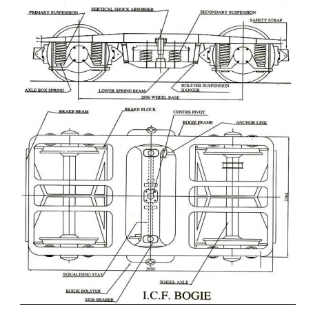
2.2 BOGIE
Main Components of ICF Bogie
UNDERFRAME:-
i) Sole bar
ii) Head stock
iii) Transom
iv) Longitudinal bar
PRIMARY SUSPENSION:-
i) Dash pot
ii) Dash pot spring
iii) Dash pot protection tube
iv) Air vent screw
v) Axle box safety bolt
vi) Axle box wing & lug
vii) Safety strap & safety loop
viii) Axle box & axle box plate
SECONDARY SUSPENSION:-
i) Bogie bolster upper plank
ii) Bogie bolster lower plank
iii) Suspension link, link pin & stone
iv) Bolster spring
v) Vertical shock absorber
vi) Safety strap & safety loop
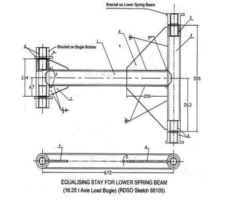
vii) Equalizing stay rod
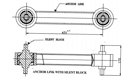
viii) Anchor link
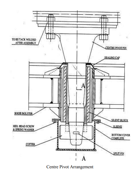
ix) Centre pivot cotter, split pin & cup
x) Silent block
xi) Side bearer housing
xii) Side bearer metal plate
xiii) Side bearer bronze wearing piece
BRAKE GEAR:-
i) Brake beam
ii) Brake beam hanger & safety bracket
iii) Brake safety wire rope
iv) Brake shoe & key
v) Floating lever
vi) Curved pull rod
vii) Equalizing truss bar
viii) Palm end
2.2.1 Features of ICF All Coil Bogie:-
1) Bogie is designed to run on Indian Broad Gauge Track (1676 mm).
2) Provision of coil spring at primary & secondary suspension so that bogie is known as All Coil Bogie.
3) Bogie Head Stock is provided with pressed T- section and sole bar is with pressed I-section, but at the location of link brackets it is in box section.
4) Transom – Previously it was in C-section but now a day it is in Box section to be more robust.
5) Wheel Base of bogie is 2896 mm.
6) Weight Transmission – By 2 side bearer located at distance of 1600 mm.
7) Guidance of bogie Lateral and Longitudinal both with the use of Centre Pivot pin located at the centre of bolster.
8) Wheel Guidance lateral and longitudinal both with the use of 2 nos. of Dash Pot guide per Axle Box Wings welded at sole bar.
9) Axle Capacity – 13 T – For Non A/C coach 16 T – for A/C coach and WLRRM coach
10) Roller Bearing – Double Roll Self Aligned Spherical Roller Bearing.
11) Axle – Solid and Straight
12) Wheel Diameter – New – 915 mm Condemn – 825 mm (workshop release size – 833 mm). Ref: Rly. Board’s Letter No. G2/ M(c)/151/2 vol. – V dated 25/01/2011
13) Shock Absorber – Provided on Secondary suspension between Bolster and lower plank (2 nos. of each Bogie).2 nos. of lateral shock absorber are being provided in ICF Bogie to be utilized for Hybrid Coach.
14) Vertical Hydraulic Dampers – 2 nos. per Axle Box Vertical telescopic hydraulic Dashpots are provided.
15) Fitment of brake block – Clasp type brake block arrangement is provided with the use of brake shoe head and brake beam.
16) 2 nos. equalizing stay rods per bogie are utilized to maintain the distance between both the lower planks and to maintain lateral thrust occurring during run.
17) Provision of Anchor link – 2 nos. per bogie with the provision of silent bushes are provided diagonally between bogie transom and bolster to work as a media to transmit the draw and braking force from trolley to body and body to trolley vice versa.
18) Piston Stroke – In conventional type Air Brake system 90 ± 10 mm and in BMBC within 32mm should be maintained.
19) Provision of Running Clearance:-
a) ‘A’ Clearance: – For 13 T – 43 +0/-3 mm, For 16 T – 27 +0/-3 mm It is a clearance to be provided between axle box crown & safety bolt.
b) ‘B’ Clearance: – It is a clearance to be provided between bolster top & bottom of sole bar that should be 40 +/- 5 mm to all type of bogie.
20) Riding index: – ICF bogie – 3.25 to 3.50
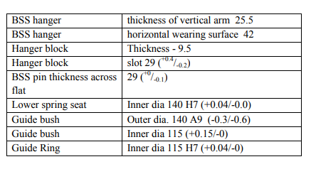
21) Truss bar Hanger: – Strength with double eye hole. New length – 235 mm. Old length – 205 mm 22) Journal Size: – Dia. – 120×113.5 mm (sleeve mounted), 120×130.5 mm (direct mounted)
23) Journal Centre: – 2159.5 mm
24) Speed: – Fit to run up to 110 kmph. (Trial has been conducted up to 140 kmph.
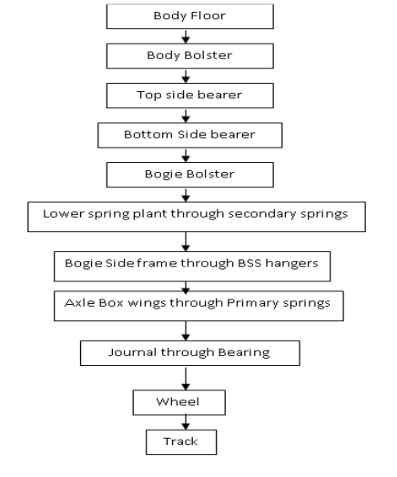
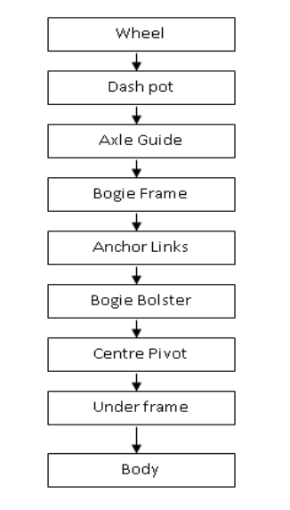
Weight Transmission of ICF Coach:
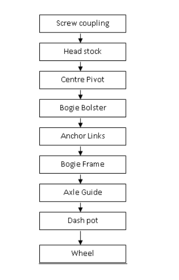
Draft Force Transmission of ICF Coach
Braking Force Transmission of ICF Bogie to Body
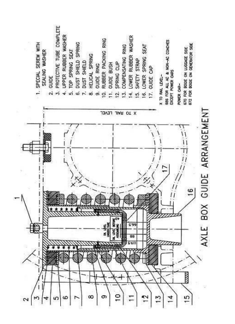
2.2.2 Axle Box Guide with Dashpot Arrangement
Axle box guides are of cylindrical type welded to the bottom flanges of the bogie side frame with close dimensional accuracy. These guides together with lower spring seats located over the axle box wings house the axle box springs and also serve as shock absorbers. These guides are fitted with guide caps having nine holes of diameter 5 mm equidistant through which oil in the lower spring seat passes under pressure during dynamic oscillation of coach and provide necessary damping to primary suspension to enhance riding quality of coach.
This type of rigid axle box guide arrangement eliminates any longitudinal or transverse relative movement between the axles and the bogie frame. The quantity of oil required for maintaining 40 mm oil level above the guide cap in modified arrangement is approximately 1.6 litres and in unmodified arrangement is approximately 1.4 litres. As it is not possible in open line to distinguish between modified and unmodified arrangements, 40 mm oil level is standardized for both.
Air Vent Screws: On the bogie side frames, directly above the dash-pots, tapped holes are provided for replenishing oil in the dash pots. Special screws with copper asbestos washers are screwed on the tapped hole to make it air tight.
Bogie Bolster Suspension: The bolster rests on the bolster coil springs – two at each end, located on the lower spring beam which is suspended from the bogie side frame by means of bolster-springsuspension (BSS) hangers on either side.
Springs: In ICF bogie, helical springs are used in both primary and secondary suspension. The springs are manufactured from peeled and centre less ground bar of chrome vanadium/chrome molybdenum steel.
Centre pivot arrangement: The centre pivot pin joins the body with the bogie and transmits the tractive and braking forces. It does not transmit any vertical load. It is equipped with rubber silent block bushes which tend to centralize the bogies with respect to the body and, to some extent control and damp the angular oscillations of the bogies.
Side Bearers: The side bearer arrangement consists of a machined steel wearing plate immersed in an oil bath and a floating bronzewearing piece with a spherical top surface, kept on both sides of 23 the bogie bolster. The coach body rests on the top spherical surface of these bronze-wearing pieces through the top side bearer at the bottom of the body-bolster. The whole arrangement is provided with a cover to prevent entry of dust in the oil sump.
Wear limit for wearing plate:
New size: 10 mm Condemning size : 8.5 mm
Wear limit for wearing piece:
New size: 45 mm Condemning size : 42 mm
Anchor Links: The floating bogie bolster which supports the coach body is held in position longitudinally by the anchor links which are pinned to the bolster sides and the bogie Transoms. 24 One anchor link is provided on each side of the bolster diagonally. The links can accommodate vertical movement to permit the bolster to rise and fall. The links prevent any relative longitudinal movement between the bogie frame and coach body. They are designed to take the tractive and braking forces. The anchor links are fitted with silent block bushes.
Silent Block: This is a synthetic rubber bush fitted in anchor link and centre pivot of ICF bogies to transmit force without shock and reduce noise.
Bolster Spring Suspension (BSS) Hangers: In the secondary suspension, the bolster is supported on helical coil springs which are placed on the lower spring plank. The lower spring plank is suspended from the bogie side frame through BSS hangers on hanger blocks.
Shock Absorbers: Hydraulic shock absorbers with capacity of 600 kg at a speed of 10 cm/sec. are fitted on 13 ton bogie & 900 kg at a speed of 10 cm/sec. are fitted on 16 ton bogie work in parallel with the bolster springs to provide damping for vertical oscillations.
Equalizing Stays: This device has been provided on bogies between the lower spring plank and the bolster to prevent lateral thrust on the bolster springs as these springs are not designed to take the lateral forces. These links have pin connections at both ends and, therefore, can move vertically.
2.2.3 Direct Mounted Roller Bearing Arrangement
Double Row Self Aligned Spherical Roller Bearing
2.2.3.1 Roller bearing defects
Flaked, pitted, Burnt, Dented, Excessively worn and seized rollers. Smearing, Cage broken, Corrosion, Locking stud loose or broken, Over greasing, Less grease & Contaminated grease, Felt ring damaged/perished, Retainer ring broken, Excessive lateral play.
Inspection of other components related to Roller Bearing
The following components other than roller bearing should be inspected during roller bearing maintenance in the workshop. Axle end holes, End locking plates, End locking bolts, Retaining Ring, Collar, Felt ring, Rear and Front Cover, Axle box housing
2.3 Draw & Buffing Gear:
2.3.1 Draw Gear:
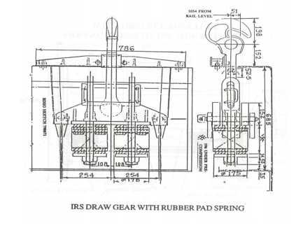
It is a vital component of rolling stock, which is utilized to connect one rolling stock to the adjacent rolling stock to form a train & also to transmit draft forces from engine to last vehicle. It is provided in the centre of the body in the under frame head stock at both the ends. Mainly two types of draft gear are being utilized in Indian Railways.
Conventional Draft Gear and Centre Buffer Coupler
2.3.1.1 Main components of conventional draw gear:
Draft Hook Draft Links Draft Key
Draft Spring/ Draft Pad. Cotter Washer
Bent Pin (U-Pin) Hexagonal Nut Screw Coupling
2.3.1.2 Parts of Screw Coupling.
1. Link
2. Bent coupling link
3. Screw
4. Bent coupling
5. Lever 6. Trunnion
7. Trunnion
8. Snap head rivet dia 8 x 85
9. Pin 60 x 218
10. Collar
11. Snap head rivet 12 x 95
12. Collar
13. Snap head rivet 6 x 70
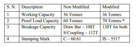
In 1984 use of Enhanced Screw Coupling was started, which was again modified in 1998. To identify this coupling a Dumble mark is stenciled at both the side of coach end body.
Length of coupling when fully opened – 997 mm
Length of coupling when fully Tight – 751 mm
Modifications:
Note: *Proof Load Capacity of Enhanced Screw Coupling is increased from 70T to 75T. This must be used in all coaches including 24 coach trains.
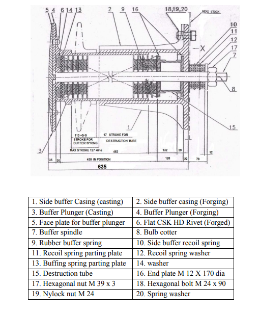
2.3.2 BUFFING GEAR:
Two nos. of buffers are provided on body head stock on both ends to absorb the longitudinal impacts during run, these are fitted at adistance of 1956 mm. The buffers also transmit buffing forces during pushing to its trailing end stock
The main components of Buffing Gear are as under:-
1. Buffer Plunger
2. Buffer Socket with securing bolt
3. Buffer Spindle & Plug
4. Buffing Pad
5. Destruction Tube
6. Recoil rubber Washer
7. Washer
8. Nut & Cotter
Mainly Buffers are of two types:-
Long Case Buffer – Length from head stock – 635 mm
Short Case Buffer – Length from head stock – 458 mm (4 wheeler)
Other data:
Max. Height in Empty condition – 1105 mm
Min. Height in Loaded condition – 1030 mm
Minimum buffer height of coaching stock should not be less than 1090 mm at the time of releasing of coach from POH Workshop.
Allowed variation in height at same end – 64 mm
Allowed variation with adjacent vehicle – 75 mm
Max. Plunger Travel – 127 mm
Min. Plunger Travel – 51 mm
No. Of Buffing Pads per Buffer – 14 to 16 Nos.
Capacity of Buffing Pads – 1030 kgm
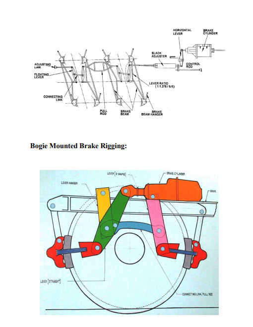
2.4 Brake Rigging Brake rigging is provided for transferring the braking force from the brake cylinder to the wheel tread. Brake rigging is different for Bogie mounted brake system and under frame mounted brake system.
Coach under Frame Mounted Brake Rigging:
In 16.25 t axle load bogie the four levers used in bogie brake rigging are each with lever ratio of 1:1.376 hence the total Mechanical advantage in a bogie is 5.504.
In 13 t axle load bogie the four levers used in bogie brake rigging are each with lever ratio of 1:1 hence the total Mechanical advantage in a bogie is 4.
Bogie Mounted Brake Rigging:
The following parts are used in the Brake Rigging.
Lever- Straight, Lever- Z shaped, Lever Hanger, Connecting Link.
Bogie brake rigging has been modified to incorporate a total mechanical advantage of 7.644 per bogie for Non-AC coaches and 8.40 per bogie for AC coaches
Brake rigging of BMBS is discussed in detail in the BMBS chapter
2.5 Maintenance
Coaching Maintenance Depots.
According to number of based coaches (holding Capacity), depot is classified into three categories.
Sr. No Depot Number of based coaches
1 Minor 50 to 100
2 Medium 100 to 250
3 Major Above 250
Standard Facilities:
1. Pit line for examination and repairs of coaches
2. Sick line with covered accommodation
3. Office & store facilities
4. Machinery & plants
5. Covered Accommodation:
Length of track under covered accommodation for any type of sick line must be at least 4% of the holdings of the depot (based coaches). The working space required for each coach is 35 m. Track length should not be less then 140m for any type of sick line.
It is essential to provide 50% track length under a covered area with pit examination facilities with proper light arrangement inside the pit. The pit also is ensured that it is provided with drainage facilities with 1% inclination & required number of man holes. Electric hoist of capacity 3 to 5 tonnes should be made available to cover the sick line across the track.
The width of the covered accommodation should be normally 15 meters covering two tracks under it. The distance between two centre lines of tracks should not be less than 7.5 meters. It should be ensured that proper space is provided beside the track for free and easy movement of transport vehicles like fork lift, lustre truck, trolleys, truck, etc.
Entire covered accommodation must have adequate lighting arrangement for workers to work without eye strain.
Machinery and Plant: To avoid heavy manual labour, wastage of manpower and to provide efficient working environment in depot, suitable adequate machinery and plant is required as under:
Synchronised whiting jacks, Coach shunter, Welding plant 200 amp capacity, Gas cutting & welding equipment, Vacuum exhauster, Air compressor (350cfm), 2 tones tram beam hoist, Sewing machine, Light Commercial Vehicle, Wood cutting saw 37 machine, Forklifts, Hand shearing machine, Portable furnace, Centre lathe, Wheel lathe, Manipulator/fixture for bogie, Ultrasonic testing apparatus, Tool post grinder.
TOOLS:
a) Pneumatic hand tools
i) Grinder,
ii) Drill,
iii) Chipper/buster,
iv) Riveter
b) Electric power tools.
i) Pop riveting tool gun,
ii) Drill,
iii) Bolt tighter/torque wrench. Hand tools including torque wrenches as required.
c) Test benches and miscellaneous items.
i) Single Car test rig
ii) DV Test bench
iii) Air Brake cylinder overhauling test bench
iv) Water tank test rig.
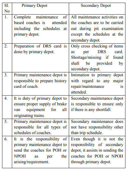
Primary Depot and Secondary Depot Sl. No Primary Depot Secondary Depot
Maintenance Schedules to be followed in Coaching Depots
Schedule is a work which is to be carried out at a prescribed interval of time. Schedule attention is required to keep the rolling stock in good serviceable condition without any failures during its life cycle for effective utilisation.
The different schedules that are carried on the primarily maintained coaching stock are:
a) Trip Schedule : After every trip
b) ‘A’ Schedule : 1 month +- 3 days
c) ‘B’ Schedule : 3 months +- 7 days
d) Intermediate overhaul (IOH) : 9 months + 30 days
e) Periodical overhaul (POH) : Once in 18 months (After 24 months for newly built)
f) Special Schedule : As prescribed by each railway
Primary maintenance schedules are required to be carried out by the base depots to which coaches are allotted. In emergency, due to any reason if the coaches cannot reach their base depots and schedules become due, A & B schedules should be undertaken by the Coaching depot where the coaches are available.
2.5.1 Trip Schedule:
Trip schedule attention is given after completion of every trip. It has to be attended both by primary and secondary depots. The coach need not be detached from the rake during trip schedule attention.
Following items are given attention during the trip schedule:
Thorough examination of all under gear parts, lubrication of all moving parts, and complete examination of buffing & draw gear is done for its proper functioning. Ensure easy operation of coupling, proper examination of primary and secondary suspension arrangement, Ensuring there is no leakage in dash pot and maintaining prescribed oil level. Ensure intactness of safety strap and safety loop. Examine the condition of springs and shock absorber. Properly examine suspension link bracket, BSS hangers, pin & hanger blocks. Examine the equalizing stay for its proper securing. Examine the proper securing of bolts & cotters & silent bushes of centre pivot. Ensure the required level of oil in side bearer. Changing of worn out brake blocks & pins and adjust the brake rigging to ensure prescribed piston stroke. Conduct Rake test as per the procedure, and ensure 100 % brake power, testing of alarm chain apparatus.
Wheel profile and thickness should be visually examined and gauged in case they appear to be near condemning limits. Ensure thorough cleaning of coach from inside & outside and disinfection of toilets after cleaning. Examination of all pipe joints & other fittings for leakages & ensure filling of water tank after attention of leakages. Examine for proper opening & closing of vestibule doors and proper fitment of fall plates. Ensure intactness 41 of all amenity & safety items. Prepare DRS card & brake power certificate.
2.5.2 Schedule – A:
Schedule `A’ attention is required to be given every month with a tolerance of 3 days at the nominated primary maintenance depot within the normal primary maintenance time on a washing/pit line. A coach need not to be detached from the rake for Schedule `A’ examination unless it requires such repairs which cannot be attended to on the washing line or within the prescribed maintenance time on the washing line. Following items are given attention during ‘A’ schedule:
All items of trip schedule
Thorough inspection of brake pipe, feed pipe and branch pipes connecting brake cylinder, distributor valve, Auxiliary reservoir and also hose coupling for leakage and give required attention. Carry out manual brake release test on every coach to ensure proper functioning of release lever of distributor valve. Micro switch of ACP should be tested by electrical staff for proper functioning. Clean Dirt collector filter with kerosene and refit. Test the working of slack adjuster in under frame mounted air brake system. Repair/Replace the defective slack adjuster. Examine loops/ brackets and their securing devices and rectify. Examine for wear of brake hanger pins, brake blocks and brake heads and replace if required. Thorough check and repairs of SLR doors for easy and smooth operation and correct alignment of all wearing parts, loose screws etc. Intensively clean the coaches. Ensure intensive cleaning of lavatory pans and commode with specified cleaning agent and thorough flushing of water tanks. Checking of 42 water pipes, flush pipe, flushing cocks, push cocks, etc., for ease of operation and free flow of water. Thorough dis-infection of all compartments. Thorough inspection and repairs of draw gear and buffers. Oil in hydraulic dash pots should be checked to detect oil leakage from them through defective seals or through vent screws. Add/replenish with specified grade of oil if oil level is below 40 mm in tare condition to ensure better riding comfort. Similarly oil in side bearer baths should be checked, if the oil is below the plug, replenish with specified grade of oil so that wear plate is fully covered by oil. Inspection and repairs of commode chute. Thoroughly check sliding doors and vestibule doors for easy and smooth operation and correct alignment, lubricate all moving parts. Thorough cleaning of chimneys of dining cars, buffet cars, tourist cars and inspection carriages by wire brushes.
2.5.3 Schedule – B:
Schedule `B’ is required to be given once in three months with tolerance of 7 days at the nominated primary maintenance depot within the normal time allowed for primary maintenance on a washing line in rake. Coach need not be detached from the rake for purpose of this examination unless it requires such repairs which cannot be attended to on the washing line or within the prescribed maintenance time on the washing line.
The following items of work should be attended.
All items of A schedule
Painting of lavatories from inside. Thorough inspection and repairs of brake gear components. Examination overhauling and testing of alarm chain apparatus. Thorough checking of trough 43 floor, turn under, etc. from underneath for corrosion. Touching up of painted portion, if faded or soiled. Testing of guard van valve.
New Policy (Recommendations) for enhancements of POH/IOH schedules of Coaching Stock.
The revised POH periodicity from 12 to 18 months is applicable to all Mail/Express coaches also. A marking on the coach below return date shall be specified to distinguish 18 months periodicity. The general sequence of Schedule will remain as per existing coaching maintenance manual.
The items of trip schedules; ‘A’ and ‘B’ schedules will remain same. The coach will be given 2 quarterly schedules (B Schedule) before IOH.
The work specified for IOH schedule to mechanical & electrical work in appendix C & D respectively as specified by CAMTECH Pamphlet No CAMTECH 2008 coach POH/1.0 in jan2008 shall be followed.
Technical circulars/pamphlets issued by RDSO with regard to schedules on time to time shall be followed for necessary modification and replacements.
The requirement of bogies for unit exchange shall be planned as per the arising of IOH keeping two bogies spare considering the transportation time from the workshop.
The periodicity of overhauling of DV is changed from 24 months to 18 months (during every POH) Work shop to switch over to PU painting during POH in workshop as advised by RDSO.
2.5.4 Intermediate Overhauling (IOH):
IOH is required to be given every nine months + 30 days at the nominated primary depot. Coaches have to be detached from the rake and taken to Sick line for IOH attention. Coach that is detached for IOH is taken over to the washing line for cleaning, lubrication and minor maintenance.
The following items of work should be attended for newly built/passenger coaches at the depot during IOH;
All items of Schedule `B’
Thorough repairs of running gear duly running out of bogies. After lifting and running out of bogies, the bogies/under frame members and body including trough floors of integral type coaches should be thoroughly examined and all parts of running gears are repaired/ replaced as necessary.
The bogie frames should be particularly checked to detect damage, cracks or deformation and necessary repairs carried out. Where it is not possible for the maintenance depot to give attention to such heavy repairs or are prohibited to be done in the maintenance depots, the bogies should be sent to the shops for carrying out these repairs. The detailed table of maintenance activities to be carried out during IOH schedule is enclosed as appendix-G. Touching up damaged paint on coaches both outside as well as inside. Thorough cleaning and removal of dust, rust, dirt, etc., accumulated at the pillars through the turn under holes, with coir brush and compressed air. Thorough examination and repairs of upholstery, cushions, curtains, etc. Thorough examination and attention of all Doors and window shutters, for safety catches, safety latches, staples and hasps for ease of operation. Thorough 45 checking and repairs of UIC vestibules, their rubber flanges metal frames, doors, fall plate, locking gear, etc., for ease of operation and safety. Thorough checking and attention to all cracks and worn out portions of flooring in the compartments. Engineer (C&W) of Primary Coaching Maintenance Depots should be fully familiar with the vulnerable areas of ICF coaches for corrosion, viz., sole bar at doorways, lavatories and its adjoining areas, corridor portion etc. special concentration shall be given to SLRs which are more prone for corrosion as it is used in transportation of Fish, Salt, etc. For facilitating inspection of sole bars even spaced elongated holes of (215×127 mm) are already provided in the turn under.
Special attention should be given for the following:
Pocket between sole bars and turn under should be thoroughly cleaned through the inspection opening of the sole bars and inspected with the help of torch light or inspection lamps. Drain holes provided in the trough floors should be kept clean and unclogged. During the cleaning of these drain holes any accumulation of water is noticed, the affected area should be very carefully inspected for possible corrosion.
Air brake system maintenance:
Check brake cylinder for loose rocker arm plate on Bogie mounted Brake Cylinder and change if found defective. Brake cylinder should be checked for smooth functioning and prescribed stroke. Defective brake cylinders shall be sent for repairs. Guard’s van valve should be tested for operation. Test BP & FP air pressure gauges with master gauge and replace if found defective (all the gauges to be calibrated once in 6 months).A set of two master gauges should be kept for this purpose at every Primary 46 Maintenance Depot and each master gauge should be sent one after the other to the workshops for testing, repairs and calibration. Thoroughly clean filter of Dirt collector in kerosene or replace on condition basis. Check working of PEASD & PEAV by hearing the hissing sound of exhaust air. After resetting with the help of key the exhaust of air should stop. Replace the defective PEASD/PEAV. Conduct Single car test of the coach with Single car test rig and record the parameters in the prescribed pro-forma. The date of intermediate lifting should then be stencilled at the appropriate place in schedule chart on the end panel
Note: Intermediate Overhauling of Shatabdi / Rajdhani Exp. Coaches are to be attended in nominated workshops only.
Intermediate overhauling of newly built coaches are to be attended after 12 months in the depot duly replacing the wheels with repaired/UT tested wheels from work shop
Lifting of the Body from the bogie:
The coach body shall be lifted by using;
a) 4 no. of Mechanical Jacks (capacity of 25 T each) OR
b) 4 no. of Hydraulic jacks (capacity of 20 Ton each) OR
c) 2 no. of Electrical Operated Travelling Crane (capacity of 20 T/25 T each) OR
d) 4 no. of Whiting jacks (capacity of 20/25 T each)
Other Tools required:- Trestles, Complete set of Spanners, Complete set of Gas cutting & welding equipment, Different types of hammers, Wooden Wedges & Packing and Tool kit
Items to be disconnected before lifting of the body:
Remove of centre pivot cotter [If lifting is being done by E.O.T cranes or whiting jacks]. Unscrew and remove centre pivot studs [If lifting is being done be mechanical/hydraulic jacks], unscrew air vent screw of dash pot. Disconnect Dynamo belt, S.A.B pull rod, lateral shock absorber if connected, axle box safety loops etc.
Remove commode chute and dummy carrier if it is infringing, foot board if required.
Insert required thickness of wooden packing between upper portion of bolster & Bogie frame.
Following are the causes of low buffer height in ICF coaches;
Wear of wheel. Loss in stiffness of coil springs provided in primary and secondary suspension. Wear in Bronze wearing piece and wear plate of side bearer. Wear on link brackets, stone & pin provided on secondary suspension arrangement.
Procedure for buffer height adjustment in ICF coaches:
To achieve required buffer height standard size of wooden packing pieces are used which are provided below the coil springs of primary suspension as given under.
New Wheel dia :- 915 mm
Condemning: – Solid Wheel: 825 mm.
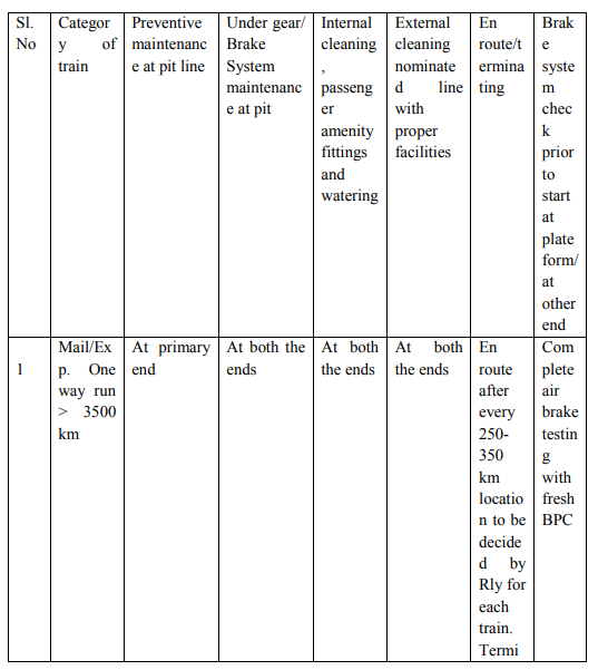
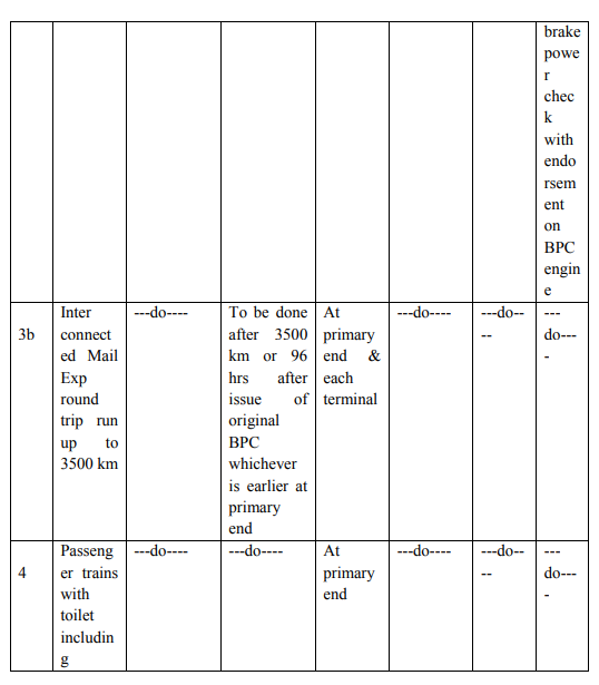
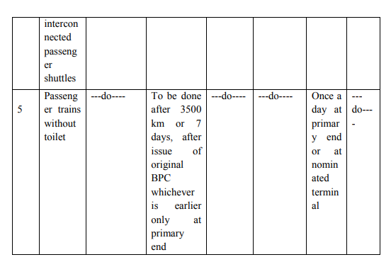
RPC-4 Revision-Jan 2007 (No. 95/M/C/141/1)
Sub: – Revised maintenance pattern of coaching train- running up to 3500 km in round trip with terminal attention at the other ends.
Note: – Internal cleaning, passenger amenity attention and watering may be done at platform line or nominated stabling line provided stipulated facilities are available at such line, in case the rake is stabled in yard for more than 6 hrs, positive safety arrangements should be made for the rake and in case the security is considered inadequate, the rake should be taken to pit line for attention to under gear as given under column (4) above.
FACILITIES REQUIRED FOR MAINTENANCE OF 24 COACH TRAINS
(Railway Bd.’s letter no. 98/M(C)/137/19 Pt. I dt. 28.7.99 & dt. 05.05.2000)
Infra structural Requirements:
24 coach length fully equipped pit line. High pressure jet cleaning pipeline with plant for cleaning in pit line at primary depot. Mechanized external cleaning is preferable. Water hydrants for 24 coach length at en-route watering stations with 20 minutes stoppage at nominated stations. Availability of the prescribed air brake maintenance and testing equipment.
Coach Design related Requirements:
Air brake with twin pipe graduated release system
Only enhanced capacity draw gear and screw coupling to RDSO sketch No. 79061 and 79067 are to be provided on the rake.
Maintenance Practices and system related requirements:
The integrity of the rakes to be maintained. Primary maintenance of the rake should be done in one hook without splitting. Minimum 6 hours’ time to be given in the pit for primary maintenance. Leakage rate in air brake system to be maintained within prescribed limits by using rake test rig. Provision of proportionate brake system on the locomotive in good working order. Provision of audio visual alarm system on the locomotive.
In case of double-headed diesel locos maximum traction motor current will be restricted to 650 Amperes and in case of double headed WAP1/WAP3 electric locos, the traction motor 54 current limit will be 750 Amperes as prescribed in RDSO ‘s instructions for operation of main line air brake trains – C-9408.
Operational requirements:
Communication between driver and guard should be provided through suitable means. Ensure no gap between coach buffers after tightening the coupler. No additional coach attachment beyond 24 coaches will be permissible.
Note: As per Railway Board Instruction now one occupied saloon & one parcel van can be attached with 24 coaches rake.
2.6 EXAMINATION OF TRAINS Ref: IRCA Rule Book Part – IV (Ch. 3)
Rolling In Examination:
There are certain types of defects in rolling stock which can only be detected during the motion of train. To detect such type of defects, rolling in examination is adopted. This examination is carried out on all pass through trains and terminating trains. To carry out Rolling in examination, C & W staff and supervisor will take position on both sides of platform / line in which train is being received.
During examination following defects are detected:
- Unusual sound due to flat faces on tyre of wheel in any vehicle of train.
- Whistling sound from bearing, if unattended that can lead to hot box.
- Hanging part or loose fitting on the vehicle.
- Any Spring broken. Brake binding on any vehicle. Any component of spring suspension like bracket loose/broken etc.
- Any abnormal behaviour of vehicle during run.
- Any other defects which can affect the safety of the train.
Rolling Out Examination:
The procedure of conducting Rolling out examination is similar to rolling in examination. Supervisor and staff will take position for conducting examination ahead of engine and ensure that the brakes of all vehicles are in released condition and any other defect that can be noticed like in Rolling in examination and could have leftover during the previous examination and can hamper the safety of the train.
Sr.DME/ DME in charge shall nominate the location for carrying out Rolling in/Rolling out examination after personal inspection of site.
While nominating the site following should be kept in view:
Site shall provide unobstructed view of under gear from both sides.
- Speed of the train shall not be more than 30 Kmph. The track should not have any rail joints at the location, It should cover the entire length of train.
- Should have adequate space for arrangement of shelter for staff.
- It should be ensure that proper lighting arrangement is provided on both the sides of the track at nominated spots 56 for examination of under gear parts during night. Focusing of lights shall be done by keeping a coach on the line and adjusting the angle of light to illuminate under gear and bogie.
Examination of originating trains:
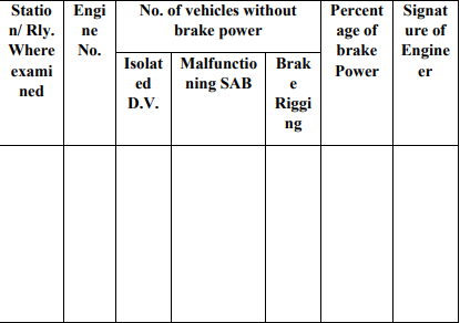
All trains must be examined by the mechanical train examining staff before dispatch to ensure that all coaches in the train are fit to run, without rejectable defects (for rejectable defects, please refer to IRCA Conference Rules, Part IV). Station Master (SM) shall handover part B & C of check memo (T431) to Senior Section Engineer (C&W) after placement of the formation in pit line for Examination, cleaning and watering. After carrying out all necessary examination and work, SSE (C&W) shall communicate fitness of the train to Station Master by giving part C of T431 duly getting acknowledgement in part B. The Station Master shall not dispatch the train unless the fitness certificate is received from SSE (C&W).
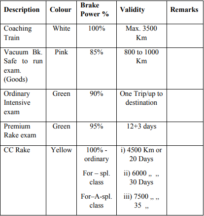
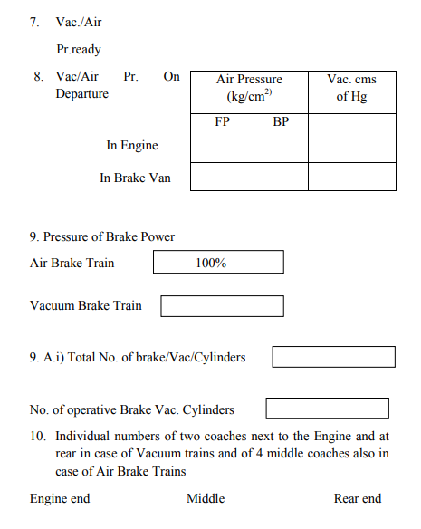
The level of the air pressure/vacuum on the train engine and the brake van gauges as well as the percentage of operative cylinders should be recorded on Brake Power Certificate and signed by Junior Engineer/C&W, Driver and the Guard of the train. Trains which have been attended on pit line should have 100% brake power and no train shall be allowed with an inoperative/defective Brake cylinder on any coach after pit attention. Trains which are attended on platform or where secondary examination has been dispensed with or en-route should have minimum 90% brake power.
En route/Terminating Examination of Passenger Trains:
Rolling in examination of the train has to be conducted for the terminating trains. After train comes to halt, it should be ensured that the train is protected from both the sides (with the stop board/red flag during day time and red lamp during night time) before commencing the examination of the train. It should be ensured that a suitable indication board is placed at conspicuous location visible to the driver indicating that C&W staff is at work. Temperature of the axle boxes should be checked & recorded preferably with the help of the Non contact infrared thermometer. Brakes of the coaches to be released manually and ensure complete release by physically moving the brake beam. Other under gear parts should be examined visually to ensure that the train is safe to run further. Repairs if required should be carried out on pass through trains by taking shortest required time to avoid detention to train to the extent possible. Lavatories of the coaches should be properly cleaned using High pressure water jet machine provided at nominated stations during halt of the train. Any complaint from passengers should be attended promptly to the satisfaction of the passenger. After attending to any required repairs only stop board/red flag should be removed. C&W control should be informed about any out of course work done. C&W control shall repeat the out of course work done to the Primary Maintenance (PM) depot after corrective action. At the train examination stations where locomotives are changed on through trains, the level of air pressure/vacuum created on the locomotive and brake van gauges should be recorded on the BPC. The inoperative/blanked cylinders, if any, should also be written in the certificate for their information. This certification should be an endorsement on the 58 original brake power certificate; no fresh brake power certificate needs to be issued.
Pit Examination of Passenger Trains:
- Related to safety: Protect the Examination line. Thorough examination and repair of under frame, Bogie, Brake gear, Draw & buffing gear. Test and repair of Vacuum / Air brake system for Brake power including test/repair of Passenger alarm system. Lubricate all moving and rubbing parts. Give preventive maintenance schedule attention for the coaches except IOH.
- Related to amenities: Dry sweeping, Cleaning, Swabbing, Watering, Pipe fitting work, Trimming work, Carpentry work, Padlocking, Painting.
2.7 WASHING AND CLEANING OF COACHES:
Wherever washable aprons are available on the platforms, the time available before the terminating trains are pulled out from platform and backed to the pit line/yard, should be utilized for inside sweeping and toilet cleaning.
External Cleaning / Washing
- Place the rake/coaches on the washing pit provided with equipments required for washing and cleaning. It should be ensured that the rake/coach is protected with proper board/signal for safety of the staff working and to prevent 59 movement/disturbance in the activity. Scotch blocks with locking arrangement should be used to protect lines and keys should be kept with SSE(C&W) till the time rake is under maintenance.
- Before starting washing and cleaning of side wall, ensure that the glass shutters and louver shutters of that side are lowered. Remove dirt/dust accumulated on shutters by compressed air or duster.
- Remove old reservation charts/labels on the body panels. Splash water on old charts so that they are wet and can be easily removed. Care should be taken to avoid any damage to the paint.
- The cleaning solution should be spread/rubbed with nylon brush or sponge brushes and then rubbed thoroughly to clean the panels. Extra attention should be given to oily and badly stained surfaces. Use recommended solutions for cleaning as per RDSO specification No. M&C/PCN/101/2001 or use cleaning agents approved by CME of the Railway.
- Destination boards may be removed and cleaned with brush/duster.
- Clean the external surface by high pressure jet where facilities are available.
- All exterior panels including end panels should be hosed with water and brushed with diluted soft soap (detergent solution). The strength of the solution may be increased or decreased according to RDSO specification M&C/PCN/101/ 2001.
Cleaning of Toilet:
- Before starting cleaning of toilets ensure that all repairs in the toilets have been carried out and after cleaning no employee should enter in the toilet.
- Doors and walls should be cleaned with water sprayed by high pressure jet up to waist level. Apply specified solution and rub thoroughly with sponge brush/ nylon bristle brush.
- Indian style lavatory pans have to be cleaned by thorough rubbing with concentrated solution of recommended cleaning agent. Western style commode shall be cleaned similarly, however due care should be taken that the cleaning solution does not fall on commode lid which may damage/spoil it. The flooring should be rubbed with nylon bristles/sponge brush and cleaned with recommended cleaning agent. The drain holes should be cleaned thoroughly for easy discharge of water.
- The mirrors in toilet should be cleaned with light wet cloth. Recommended solution should be used for cleaning the dirty portion of glasses.
- After all the washing and cleaning in the toilets mentioned above, the toilets should be thoroughly cleaned with water jet and water should be flushed out. All fittings and floor should be wiped dry with a cloth. After cleaning, spray deodorant in the toilet to remove the bad odour.
Internal cleaning of upper class AC and sleeper coaches:
- Empty the magazine bag and waste from dust bin. Sweep the whole coach with broom in sleeper coaches. Clean the floor of AC coaches with vacuum cleaner.
- Remove dust from floor, berths/seat, and magazine nylon wire mesh bag fitted on panels and fan guards with duster. Use of vacuum cleaner is recommended in such areas.
- Also remove dust/dirt from under the berths, window sill, and sliding door, railing corner and all corner & crevices of coach interior with vacuum cleaner if provided. Ceiling panels, wall panels, cushion berths, fittings, table top, etc. should be cleaned with duster and stain marks on these should be removed by use of recommended soft detergent.
- Aluminium frames, strips, and other metal fittings, etc. should be cleaned with recommended cleaning agent. FRP window frames, louvers, etc. should be cleaned with recommended solution and rubbed out by nylon brush or sponge /duster to remove stain marks. Alarm chain handle and its holding bracket should be washed and cleaned. The PVC flooring should be rubbed with nylon bristles/sponge brush and cleaned with recommended cleaning agent.
- In AC coaches, the amenity fittings and toilet fittings such as coat hanger, stools, arm rest, foot rest, towel hanger, etc. should be cleaned with duster. Stains on these items should be removed with recommended detergent solution.
- The compartment carpet should be cleaned with vacuum cleaner. Every month, the carpet should be cleaned thoroughly by taking it out from compartment and if necessary they should be dry cleaned in every three to four months. Before re-laying the carpet, the compartment floor should be thoroughly cleaned. Spray recommended air freshener in the coach. No employee should be allowed to enter the coach for any purpose/work after complete cleaning
- Curtains in the AC Coaches and Tourist Cars should be removed for periodical washing and cleaning. Faded and damaged curtains should be replaced on condition basis. Precaution should be taken to prevent nuisance of cockroaches in AC coaches and pantry cars by periodical disinfestations. No repair works on Electrical train light/fan/AC) or Mechanical account should be left to be carried out after washing and cleaning of the coach.
Internal Cleaning of GS, SLR:
- Cleaning of GS, guard and passenger compartments of SLR should be done as mentioned above in sleeper coaches.
- Interior surfaces of parcel and luggage vans should be cleaned thoroughly with recommended detergent and water, and the water should be completely flushed out and make the compartment dry without any moisture.
Cleaning of buffers and screw couplings:
- Buffer plungers should be scrubbed with a scraper to remove dirt and muck. Thereafter, they should be wiped clean and lubricated with oil.
- Screw coupling threads should be cleaned with wire brush to remove all dirt and dust. Thereafter, it should be cleaned and given a light coat of oil.
2.8 EXAMINATION OF BOGIES:
Depot maintenance staff should ensure the following things in respect of proper functioning and safety of Bogie & Bogie components.
Bogie Frame:
- During every trip, and Schedule A & B, Examine visually condition of bogie side frame, transom, longitudinal etc especially at all welded locations. Examine rubber stopper and crown bolt of axle box, Axle box & Bolster safety strap for damage/ missing/ loose. Examine Brake hanger brackets for damages. Examine the brackets for safety wire rope of brake beam. Examine visually BSS hanger brackets, Anchor link brackets. Visually examine centre pivot mounting bolts, centre pivot cover and attend if needed. Side bearer oil to be replenished in A & B schedules, if needed.
- During IOH at depot, further to attending all the above items, Examine condition of wearing piece and wearing plate, oil level in side bearer oil baths and replenish if oil 64 level has gone down below the level of last thread of oil filling cup.
Primary Suspension:
- Every trip visually examines axle box springs for breakage, dash pot oil filling special screw for deficiency. Check oil leakage in dash pot through defective seals/vent screws. Visually examine axle box clearance
- During Schedule A & B, examine all items as above. Add specified grade of oil in dash pot. Visually examine and adjust axle box clearance.
- During IOH at depot, further to attending to all the above items, examine the axle guide assembly by lifting the coach and give any attention if necessary. Check axle box clearance with gauge and adjust.
Secondary Suspension:
- During every trip, and Schedule A & B, visually examine bolster springs for breakages or any other defects. Visually examine Bolster lower spring beam, BSS hangers, hanger blocks, BSS pins. Check bolster clearance between top of bolster and bottom of bogie frame. Visually examine equalising stay rods and pins (small and big) and brackets. Check and attend safety loops of Equalising stay rod. Visually check anchor links, and its securing bolts and attend if needed. Examine safety loops of bolster, vertical shock absorbers for damages and attend if required.
- During IOH at depot, dismantle Secondary suspension and measure the dimensions of spring, BSS hangers, Hanger pins, Hanger blocks and the hole in the bracket. Remove the equalising stay, measure the pins/bushes for any wear and re-grease the pins. After assembling maintain the Bogie ‘B’ dimension as prescribed.
Brake Rigging:
- Every trip, check brake gear and adjust so that the piston stroke is within the limit. Examine brake beams for breakages/damages. Check and attend brake beam safety wire ropes/safety straps. Check and attend brake shoe head and key & replace if necessary.
- Check and replace worn brake blocks. Visually inspect and replace brake hangers, brake gear pins and cotters/split pins if necessary. Visually inspect and replace damaged/missing brake gear bushes. During Schedule A & B, further to examination of the above, check and attend brake block adjuster. Examine and attend brake levers, floating lever suspension brackets
- During IOH at depot, examine all items as above. Examine and replace all brake gear components found deficient and worn out
Draw Gear:
- Every trip, Schedule A & B, check and replace damage/missing split pins/cotters/rivets. Examine draw 66 hook, draw bars and rubber pads for damages. Check condition of the screw coupling and its components and replace if required. Check condition of draw beam and locating pins on it. Examine visually draft key locking pins.
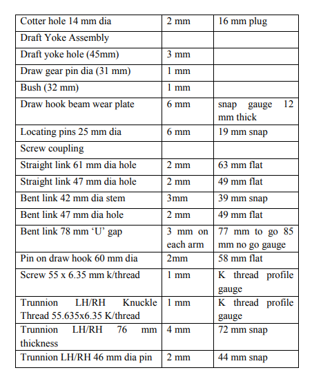
- During IOH at depot, examine all items as above, Ensure that wear on screw coupling shackle pins, trunnion pins, shackle/link holes and draw hook holes should not exceed 3 mm. Ensure that wear at any section on draw hook should not exceed 10 mm.
Buffing gear:
- Every trip, Schedule A & B, visually examine Buffer plunger for drooping, crack/wear and stroke length. Examine Buffer casing for crack and its securing arrangement.
- During IOH at depot, dismantle the buffer assembly, and check for perished pads, destruction tube, worn out Buffer face/spindle etc and attend/replace where ever necessary. Buffer alignment with head-stock should be true. Buffer projection should not be less than 600 mm and not more than 635 mm.
Wheel and axle:
- Every trip, Schedule A & B, examine visually axle box for grease oozing and warm box and any damages/loose covers. Visually examine the profile of the tyre and check 67 with tyre defect gauge if appears nearing condemning limit.
- During IOH at depot, check the wheel distant gauge for loose/tight wheel. Examine axle pulleys on the wheels
- In addition to normal checks, wheels to be checked for defects as per CMI – K 003.
Roller Bearing & Axle Boxes:
- A coach should invariably be detached from service for the following defects
- Hot axle box, damaged axle box, damaged front or rear cover, Seized roller bearing, Coach involved in accident, derailment, fire, flood etc.
- Care should be taken not to keep a coach fitted with roller bearing stationary for a long time. Coaches stabled for a long time should be shunted up and down at regular intervals.
- Coaches fitted with roller bearing should be ensured that:
- No wash basin drain hole / discharge pipe is directly above the axle box. The front and rear covers of the axle boxes are not damaged, cracked or loose. Clearance between axle box and wheel is such that the axle box does not rub against the wheel. Brake gear is properly adjusted to avoid possibility of brake binding.
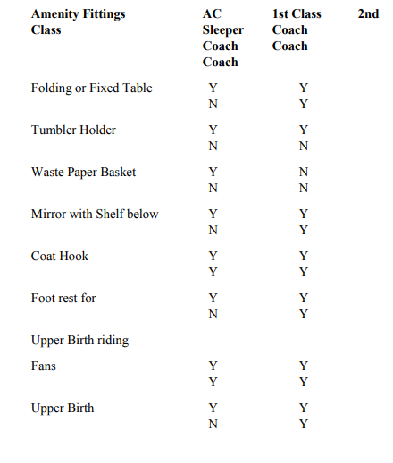
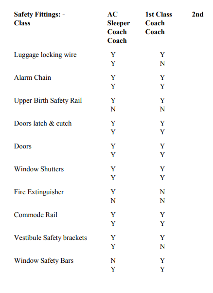
2.9 SAFETY & AMENITY FITTINGS
The fittings which are fitted in the coach for safety of passengers & their luggage are called as “Safety Fittings“. The fittings which are provided inside the coach for comfort, Luxury and also for non-strenuous journey of the passengers are called as “Amenity Fittings“.
Following are some of the Safety fittings provided in the coaches:
Alarm pull chain, Internal latches on top & bottom on body side doors, Provision of pad locking arrangement from outside of body side door, Internal latch and tower bolt for compartment doors in first class, Vestibule doors/shutters with locking arrangement, Latches for window shutters, Fire extinguishers, Safety bars on all window openings, Window shutters both glass and louver, Sealed window glass for AC coaches, Frosted glass shutters for toilets.
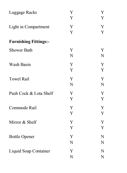
Following are some of the Amenity fittings provided in the coaches:
Lights and fans inside the coach, Reading light with switches for upper class coaches, Charging socket out let in upper class coaches & sleeper coaches, Cushioned berths and seats & back rest, Luggage racks, Folding or fixed tables, Roof ventilators, Tumbler holder, Dust bin, Footsteps in sleeper coaches and foot rest for chair cars, Notices, Mirror with shelf, Coat hook, Magazine pouch, Bottle holder, Wash basin, Wardrobe with fixed hangers for 1st AC, Rings below berths for securing luggage, Shower bath, towel rail, flushing commode & pan, coat hook, liquid soap container, push cocks, hand rail, mirror with shelf, soap dish etc. in 69 lavatories, Destination boards, Reservation display plates, Coach indication boards.
Compartment:-
2.10 NMG COACHES
The coaches with age of 20 – 21 years or later are being converted during POH for the purpose to carry Automobile (Express). These coaches are known as NMG coaches and the rakes formed with these coaches are called NMG rakes.
Following are the features:
- Load carrying capacity is 12 ton maximum.
- Speed 75 kmph & 100 kmph Max.
- The life of such converted coach is 30 years from the date of original manufacture.
- Wider end opening of 2800 mm × 2200 mm.
- Improved adjustable internal locking and lashing arrangement to avoid damage to the vehicle during transit.
- The periodicity of POH is 24 months.
Maintenance Pattern for NMG rakes
(As per Rly. Bd’s Letter No. 91/M (C)/650/1 dated 29.5.2000)
In order to optimize utilization of NMG rakes it has been decided to introduce the following maintenance pattern:
NMG rakes may be run on goods pattern with intensive examination at both the ends, following other conditions for enroute detention in case at stabling at road side stations. In case of close circuit runs up to3500 km, the rake may be run on round trip basis. Close circuit rake must be clearly identified and should have a nominated base depot where adequate trained staff and spares should be available. Each NMG coach should be marked with the nominated POH workshop and return date. The maintenance 73 schedules of the NMG coaches will continue to be on the coaching pattern to be carried out by the base depot. Using these coaches as parcel vans for running on piecemeal basis on passenger carrying trains is strictly prohibited. Each coach should be stencilled at a suitable place on its end panel, the code of the base depot and a schedule chart. The date and station code of the depot where a particular schedule is carried out should be stencilled at the appropriate place in the schedule chart immediately when the schedule is completed.
IOH/POH periodicity of ICF coaches:
(Rly Bd letter No.2007/M(C)/141/1 Dated: 26.09.2008 & 06.08.2009)
D.O.No.2007/M/(C)/141/1 dated: 12.02.2009 by MM to all CMEs
Note: The concept of C schedule in the depots, hitherto being followed on the Railway, maybe done away with and replaced by an IOH as under.
The bogies must be rolled out and IOH schedule carried out on the bogies in the coaching depot itself with mandatory replacement of overhauled wheel sets supplied by the workshops. The attended bogies must then be provided in the same coach. The IOH schedule is applicable to all new ICF design coaches irrespective of the train category being serviced by them.
Unit exchange of overhauled bogies supplied by the workshops must be ensured.
The Bogies must be rolled out and the IOH schedule carried out on the bogies in the depot itself retaining the wheel sets, unless specific attention or change is warranted on the wheel sets. The attended bogies must then be provided in the same coach.
MAXIMUM ALLOWABLE INEFFECTIVE PERCENTAGE
Authority: Railway Board Letter No: 86-M/(N)/951/7 of 26.6.87
Following are the few items that Workshop shall ensure during POH:
- The lowest permissible wheel diameter for a coach turned out after POH shall not be less than 837 mm.
- If the buffer height requires adjustment, the load on the axle box springs should be released and the packing rings in halves shall be inserted below the axle box springs. The total height of primary springs and compensating rings should not exceed 295 mm. There should be a minimum clearance of 40 mm between the axle box wing lugs and their safety straps.
- The clearance between the axle box crown and the bogie frame should thereafter be adjusted as per the table given below:
There shall not be any leakage of oil from the side bearer. Hard ground plate in side bearer, should not be worn more than 1.0mm in thickness or ridges formed on the plate. Bronze wearing piece for side bearer, should not have worn more than 1.5 mm in thickness. Sharp edges on wearing piece should be rounded off before re-use. Dust seal cover shall sit effectively all around without any gap on the oil-bath and the sleeves slide freely on the guide to ward off dust and moisture coming in contact with the oil. The oil filling plugs should be well secured by chain to prevent it from dropping.
Equalising stay pins should not be worn more than 1 mm in dia (31 mm standard), all the bushes and washers to be replaced. Maximum dimensional clearance between the pins and bushes of brake gear should be within 1.5 mm. springs shall be subjected to load test and grouped as per the following tables.
Combined load deflection test is done
As per RDSO letter No. MC/MV dtd: 21.11.2001
The maximum diametrical clearance between the lower spring seat and guide bush should not exceed 1.6 mm. The bogie should sit evenly on the four axle boxes. The assembled bogie should be tested for normal working load and the bogie frame lugs and bogie bolster should be adjusted so as to ensure a minimum clearance of 40 mm between the lugs and bottom of safety straps.
After placing the wearing plate and wearing piece in side bearer oil-bath, each side bearer oil-bath should be filled with 2 litres of any of the following approved brands of oils.
Servoline – 100 of IOC
Yantrol – 100 of HPC
Bharat univol – 100 of BPC
Apply graphite grease on Centre pivot pin
Shock absorbers should be given a schedule overhaul, or after 4 lakh kilometers or alternate POH, whichever is earlier. The shock absorber is tested on the special purpose machine which can measure its capacity in both tension and compression by developing the resisting force at a velocity of 10 cm/sec.
Variation in diameter of wheel should be within tolerance as given below;
- On the same axle 0.5 mm
- On the same bogie 5 mm
- On the same coach 13 mm
Draw hooks and screw coupling (Stc. 60-61) should be tested at 60t and those of IS:5517 Gr. 35Mn6Mo3 should be tested at 75 t respectively.
There should be no permanent set after release of load. The draw bar should not have dimensional distortions and damaged threads. The draft key should not be bent or worn out. All the draw bar and hook should have been tested by magna-flux for surface cracks. Draw bar (Stc. 60.61) should have been load tested at 39.5 t and those of (IS 5517 Gr. 35Mn6Mo3) at 60t. There should not be any permanent deformation. The draft pads which are bulged, perished or having set to a length below 186 mm should be changed during POH (New Rubber draft pad pack to STR No.C- 9501 (Rev.2) free height along with parting plates is 208 mm and 196 mm pre compressed length is achieved after tightening the castle nut).The pads should be changed invariably as a set every alternate POH, and all the in a draw bar assembly should be from a single supplier. Draft Yoke should be free from welding cracks distortions.
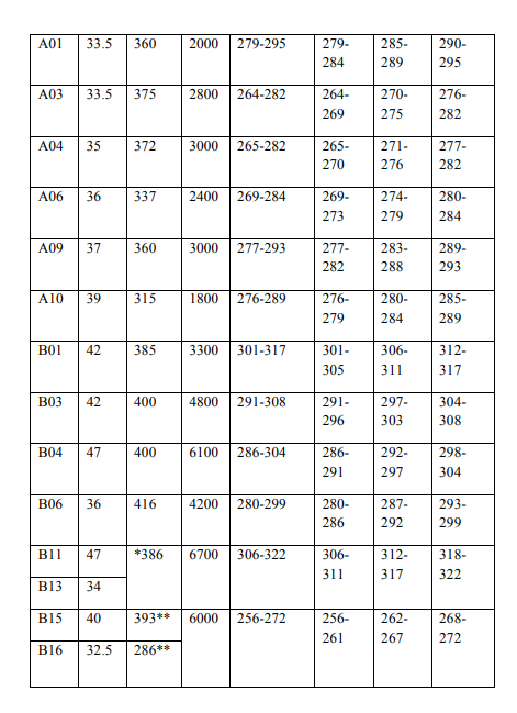
The wear on the following locations shall be within the limits given below;
The projection of the shoulder on the draw hook from the head stock after assembly should be within 92 mm – 120 mm.
The buffers should not be cracked or damaged/deformed. in buffer casing to SK 94043/94044. Rubber buffer pads should be changed if perished, or permanently set to a length below 424 mm. The pads has to be replaced as a set every alternate POH. The set should not be formed from different supplies. (Free height of rubber buffer pad pack consisting of 16 pads to STR No.9501-Ref 2 by adding required parting plate should be 484+/-2 mm. After assembling and tightening of the M39 nuts on the buffer spindle to achieve buffer projection of 635 +/- 2, the pre-compression of rubber pads along with parting plate will be 439 +/- 2 mm).
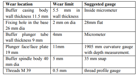
The wear limits are given in table
2.11 INDO – GERMAN MODIFICATIONS
RDSO has approved 13 modifications (7 are on brake gear, 4 on bogie and 2 on buffers) to be carried out as per Indo-German project to increase the POH periodicity and life of the components.
The reasons behind the modifications and intended benefits are given below.
Modification done on Brake gear pins and Bushes:
- In earlier design Acetal bushes were used in the brake rigging. Since these bushes were cracking and wearing at faster rate, results in frequent replacement of Acetal bushes during maintenance and POH.
- Hence to prevent frequent replacement of bushes, the brake gear bushes are replaced with Nylon 66 material. To increase the life of the bushes further, the brake gear pins are finished with N-5 ground finish and coated with Chromium to the thickness of 25 microns. The purpose of coating the pins with Chromium is that it is very good wear resistant material.
- After the above modifications on the bushes and pins, the pins practically show no wear during POH and therefore can be reused.
Modification on brake shoe and shoe key:
It is seen that the uneven wear of the brake blocks is due to the faulty design of the brake shoe key and brake head. The brake shoe key is functioning well as long as it is inserted from the top.
For design reasons, the key cannot be inserted from the top in the ICF bogies, as there is insufficient space. If the key is inserted from below, then on application of brakes it will slide downwards and loosen the binding (The slack between the key and shoe increases.)
The present brake shoe head permits the brake blocks to move up and down along the force of friction on the wheel tread due to the large clearance present between end stoppers on brake block and brake head ribs. Due to the free movement the brake block crushes the base plates and ends of ribs during brake application.
So to overcome the above problems on Key and the brake head, they have been suitably modified to have a snug fitting between the brake head and the brake block. The modified design arrests the movements of brake blocks to the minimum. It ensures square striking of brake block surface on wheel tread during brake application.
Modification on brake beam safety bracket: Brake beam safety straps provided previously ensures only marginal security. It often breaks while supporting the brake beam in case the hanger pin breaks. Hence to prevent dropping of brake beam on run in case if the brake gear pin fails, a new design of Safety wire rope is introduced in place of the safety strap.
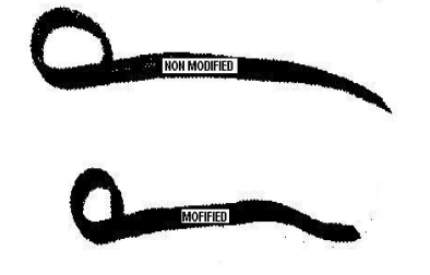
Modification on brake hanger:
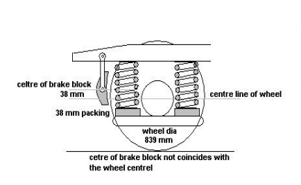
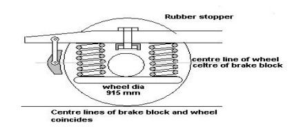
When the wheel diameter is maximum, the centre line of brake block coincides with the centreline of wheel. In this condition, the brake block gives lateral and radial force along the centre line of wheel during brake application.
- But when the wheel diameter reduces, the buffer height also reduces. To bring back the buffer height to normal a packing piece is given between the Dashpot and the Axle box.
- Generally whenever the wheel diameter reduces to 839 mm, a 38 mm packing is given between the dash pot and the Axle box, thereby raising the brake block by 38 mm from the centre of the wheel. In this condition, the brake block force is not along the centre line of the wheel but on the upper half of the wheel during brake application and there is a tendency for the brake block to mount over the wheel due to the dragging of brake block by the wheel in the direction of wheel movement.
- To prevent the mounting of brake blocks over the wheels whenever lesser diameter wheels are used, the length of the brake hanger is increased from 205 mm to 235 mm in order to make the centre of brake block to coincide with wheel centre.
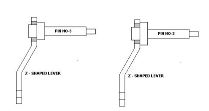
Modifications done on the Z-lever hanger pin:
- The flat size of the hexagonal portion of the lever hanger pin was 46 mm, which is smaller than that of the bush used for the Z shaped lever. This resulted in the bushes getting damaged due to the rubbing action against of the hexagonal portion of the lever pin No.3.
- To prevent the damages to the lever bushes and also working out of bushes, the flat to flat of the hexagonal portion is increased from 46 mm to 55 mm.
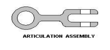
Modification done for articulation arrangement:
- In ICF coaches it was found that the spindle rod of SAB often broke due to bending of spindle while negotiating a curve. The play for the SAB is only in the vertical plane and not in the horizontal plane. Secondly sufficient support is also not provided leading to high oscillations on bad tracks. To overcome the above said defect, an articulation bracket is provided only for vacuum braked stocks, which facilitates the SAB to move laterally along with the bogie whenever it is negotiating a curve.
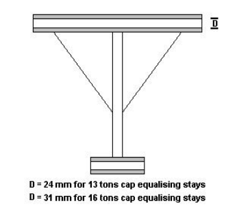
Modification done on Equalising stay:
- The 13 tonne bogies stay pins were often found in bent condition and have to be removed only by gas cutting, but there was no problems noticed in the 16 tonne bogies. It was also observed during POH that about 80% of stay rod pins of 13 tonnes bogies are received in bent and 40% have to be removed by gas cut.
- The reason is that the diameter of the pin used for 13 tons bogie is only 24 mm when compared to 31 mm diameter pin used in 16 tons bogies.
- To prevent frequent replacement, the equalizing stays have been standardized with 16 tons capacity for all the newly manufactured coaches.
Modification on Axle box crown bolt:
- During POH, it was found that the axle box housing bolt arrangement has to be replaced due to damages and also during maintenance difficulties were experienced to maintain a constant crown clearance between the bogie frame and the axle box due to working out of bolts. This is mainly due to hitting of the bolts on the run.
- To overcome the above problem, a rubber stopper is provide with the bolt to dampen the shock, to enable to adjust the clearance under the operating condition in case of wheel wear and fatigue of springs. It also enables for the easy replacement of the rubber pads without lifting the coach.
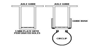
Modification done in the axle guide arrangement:
- Often the guide cap in the axle guide assembly is found dropped. The normal practice is to weld a strip with a bolt 94 and tighten the guide bush at the bottom with a nut. During run, this also drops down due to the vertical and lateral oscillation. The dropping of guide cap results in damages to the threaded portion at the bottom of the guide, since it comes in contact with the dashpot directly.
- To overcome the above problems, the guide cap is completely eliminated by carrying out two modifications on the guide. The purpose of providing the guide cap is to allow the oil from dashpot into the guide with restrictions and also to secure the guide bush in position.
- To allow the oil from dash pot into the axle guide a 5 mm plate with perforated holes is welded with the axle guide at the bottom from inside.
- A circlip is used to secure the guide bush in position.
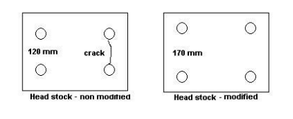
Modification done on the headstock:
- In the earlier design the vertical pitch hole distance on the headstock for fitment of buffer was only 120 mm. As the resisting area was reduced due to the lesser pitch hole distance, the headstock were getting crack. 95
- To prevent cracking of headstock, the vertical pitch hole distance for buffers on the headstock is increased from 120 mm to 170 mm
Modification on Buffer rubber pads:
- In the earlier design, 14 pads of 20 tonne-inch capacities were being used with a dividing plate interposed between them. But it was found that mixing of old and new pads lead to damage to the pads, as seating was not uniform and also leads to headstock failures. To avoid this, modified rubber pads of 40 tonne-inch capacities (1030 kg-m) of 32 mm thickness are recommended. This leads to reduction in the maintenance required for the buffer in open line.
- The modified rubber pads have increased contact area between the pads, to prevent damages to the rubber pads.
Dimensional check report for the bogie frame:
- It was found that the designed tolerance was not being maintained in the bogies during manufacturing and to avoid failure of axle guides at the joint, a dimensional check list is separately formed for non-AC, AC and power cars.
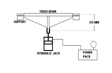
Modification done on the brake beam of Air braked stock:
- Often it was found that the brake beam was failing near the central stiffener because of corrosion due to water accumulation. Also there was no provision for hanging the brake beam with a safety wire rope from bogie headstock. To avoid this, now stiffeners of 3.15mm and drain holes are provided. As there was no proper testing procedure for accepting the brake beams, a testing procedure also is suggested.
Testing of Brake Beam:
Apply a tensile load of 12 tonnes between the brake shoe ends and the floating lever end. On 12 tonnes load, an elastic deformation of 3mm is permitted. On removal of load, the truss beam should come back to its normal position. However a permanent deformation of not more than 0.5 mm is permitted.
LATEST MODIFICATION ON COACHES
- Change in securing arrangement of anchor link, similar to that of Fiat Bogie.
- Use of Hopper type Shutters in place of banjo type frosted Shutters in toilets. Provision of ventilator with Arc shape fins with LAV for proper circulation of Air.
- Provision of Resetting Handle with wire rope on end panel for the resetting of ACP from ground itself and APD for Guard van valve and its handle. Increase of vent hole dia in PEAV from 4 to 8 mm.
- Reduced width of brake shoe head by 5 mm from inside.
- Crash worthiness of the coaches is increased by making following modification;
- Mirrors are rounded at the edges, berths are rounded in the corners, side seat backrest holding arrangement is shifted to the inner side, sunk in type mirror shelf, modified berth chain, etc.
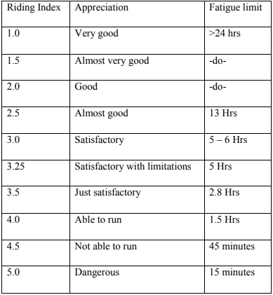
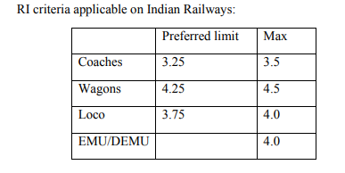
2.12 RIDING INDEX
The assumptions for the formulation of certain standards of assessing comfort is purely from the point of view of vehicle oscillations transmitted to passengers only. The human sensation of comfort is dependent on displacement, acceleration and rate of change of acceleration. Basically, these indices are function of the amplitude of vibration and frequency of vibration. In other words, the product of these values could be used as measure of comfort/discomfort.
However the sensation of smooth riding is also affected by other factors like temperature, humidity, noise, dust & various 98 psychological factors experienced by a passenger during run. The ride index is just a number with no units and its value gives us an indication of the riding comfort of a vehicle. The index is easily calculable during field trials by measuring the vertical/lateral accelerations using standard accelerometers.
Ride Index gradations are as follows:
The ride index as described above gives the average riding quality of a vehicle over the chosen length of track (generally one kilometre). However, individual acceleration peaks also have an effect on the comfort of the passengers. Accordingly, limits for maximum acceleration values have also been laid down for coaches and locomotives. For details, the Third Criteria Committee Report of RDSO may be referred.
The Following Measures Should Be Given to Maintain Ride Index in ICF coach:-
Proper checking of primary suspension arrangement. Checking free height &height variation of primary suspension springs and grouping. Ensure sufficient level of oil in the telescopic hydraulic dash pot. Gap between safety loop & axle box lug should be within limit i.e. 40 mm. proper pairing of springs on secondary suspensions. Free height of spring should be within limit. Ensure proper working of shock absorber. Proper checking of side bearer for oil level & wear on bearing piece/plate should be within limit. Proper checking of silent bushes fitted in bolster for proper matching with centre pivot.
Proper checking of buffing gears for buffer face contact. Plunger stroke should not be more than 127 mm & less than 51 mm. All securing bolts & nuts should be properly fitted. Proper checking of draft gear. Coupling should be fully tightened evenly. Other securing nuts, washers, cotters should be in proper position. Anchor links should be intact with good silent block bushes. All break gear pins should be provided with proper bushes. Dynamo pulley & belt should not be loose. It should also be ensured that there is no wheel defect such as flat faces (not more than 50 mm), deep flange, skidded wheel, sharp flange, thin flange etc. In addition, the Ride Index can also be improved by ensuring proper p/way maintenance, signal defects & good engine man ship of the driver.
2.13 CORROSION AND ITS PREVENTION
Introduction: When metals are put into use in various forms they are exposed to environment containing liquids, gases etc. As a result of this the surface of metal starts deteriorating. This type of deterioration or destruction may be direct chemical attack or electrochemical attack.
Definition: corrosion is a chemical process of oxidation with metal to its surroundings, covering it into metal oxide, carbonates, hydroxide and sulphides. Oxidation takes place only when steel surface exposed to atmosphere or moisture. Chemical reaction is as follows:
4Fe + 3O2 ——–2Fe2O3
Example: rusting of iron. When iron is exposed to atmospheric conditions rusting of iron takes place. During this exposure a layer of reddish scale and powder of oxide is formed and iron becomes week.
Effect of corrosion: Corrosion of materials is liable to performance of the product; lose their strength, ductility and certain other mechanical and physical properties.
With the introduction of all steel coaches corrosion has become a major problem. Once starts it is very difficult to control it. This requires replacement of the component. This is much costlier than to save the existing part by proper and timely attention.
Corrosion in ICF coaches: Corrosion in ICF coaches is very common. Corrosion repairs to coaches are mainly carried out during POH in workshops. Corrosion repairs are also done during 102 midlife rehabilitation of coaches that are 12 to 13 years old especially at CRWS, Bhopal next POH in 24 months.
During POH all the under frame members are thoroughly inspected to locate corroded members. Corrosion is indicated by flaking of paint, flaking of metal, pitting and scale formation. Components that is not visible from both sides such as sole bar and trough floor should be examined by tapping with a spiked hammer.
Particular attention should be paid to the more vulnerable members and locations given below.
1. Sole bars, body pillars, turn under and trough floor below lavatories in all types of coaches and luggage compartments of SLRS.
2. Sole bars, body pillars, turn under and pillars above lifting pads.
3. Sole bars, body pillars behind the sliding doors of SLRS
4. Sole bars, body pillars, turn under at the door corners & near coach body bolster.
5. Headstock
Inspection of under frame member for corrosion attention should be done as per technical pamphlet no 7602(rev: 1)
Reason of corrosion in ICF Coach:
1. Accumulation of water, dust and salty discharge under luggage compartment in coaches.
2. Incorrect fitness of side panels.
3. Galvanic cell formation between steel and aluminium near window area.
4. Seepage of water at corners and ends due to water accumulation on floor.
5. In sufficient surface preparation before welding.
6. Frequent use of concentrated acids for the cleaning of toilets.
7. Leaky push cocks, flusher valves.
8. Missing/defective commode chutes resulting in splashing of toilet discharge leads to corrosion of under frame members.
9. Carrying of perishables items like fish in SLRS and Parcel vans and insufficient cleaning after unloading.
10. Entry of water through gaps in window sills.
11. Cracks in body panels and roof left unattended.
12. Painting defects left unattended.
13. Damage to under frame and trough floor due to flying ballast in dynamic condition.
14. Acid spillage from batteries.
Need of Corrosion prevention:
1. To avoid premature detachment of coaches and wagons in service.
2. Corrosion makes wagons unfit for loading. This has a bad effect on earning capacity of railways.
3. There will be a shortage of wagons fit for loading if wagons are detached for corrosion repairs.
4. Detachment of coaches for corrosion repairs has an adverse effect on the normal composition of trains.
5. In monsoon season seepage of water through corroded panels spoils the consignment and railway is forced to pay compensation for the damage.
6. Manpower material and time involved in corrosion repairs can be controlled through proper anticorrosion measures.
7. Losses of railway revenue i.e. losses to the nation.
Always Remember the Saying: – ‘A STICH IN TIME SAVES NINE’ while dealing with corrosion.
Inspection during POH:
1. Inspection of sole bars, body pillars and turn under: Examine visually and with the help of a spiked hammer from below the coach and the inspection holes in the turn under. If corrosion is suspected at places without inspection holes 100mm dia hole should be cut at the bottom of turn under for examination. If corrosion is noticed in the bottom half of the sole bar the trough floor to be cut to a width of 300mm for inspection. In case of heavy corrosion the side wall to be cut to a width of 500mm.
2. Inspection of headstock: Examine visually inner and outer headstock, stiffening behind buffers and the junction of sole bar and the headstock for corrosion. Examine the base buffer assembly carefully.
3. Trough floor: Examine trough floor adjoining the lavatories and under the luggage compartment of SLRS and Parcel vans for corrosion with the hammer.
Corrosion Repairs During POH:
1. Repairs to under frame members: Repairs to under frame members should be carried out as per RDSO pamphlet no C7602 for ICF coaches. Corrosion resistant steel sheet for trough floor, pillars, sidewalls and roof should conform to IRS M-41-97. Electrode IRS class B2 of approved brands. Paint red oxide zinc chromate primer is-2074-62. Bituminous anti corrosive solution to IRS-P30-96.
2. Repairs to Headstock: Only 8mm thick sheet is to be used headstock repairs.
3. Repairs to Sole bar: The new sole bar section to be welded from both inside and outside.
4. Repairs to Side Wall Members: For repairs to side and end wall members’ interior fittings interior panels & window frames are to be stripped. Repairs to be done as per RDSO sketch No. 76019.
5. Repairs to Trough Floor: For trough floor repairs plywood flooring to be stripped. Repairs to be done as per RDSO instructions.
6. Repairs to Roof: Special attention to be paid at locations where gutter mouldings are and where ventilators are fitted. RDSO instructions to be followed.
HOW TO MINIMIZE CORROSION
Corrosion in rolling stock cannot be eliminated altogether. Hot and humid conditions in our country are helpful for corrosion. A change in climate also has an adverse effect. However timely action during repairs and maintenance will minimize corrosion.
DURING POH
1. Thorough inspection giving extra attention to areas prone to corrosion.
2. Turn under repairs to be carried out with 5mm thick plates.
3. Only 8mm thick SS sheets to be used for head stock repairs.
4. Use stainless steel trough floor and inlays for toilets.
5. Use of 13mm comprege floor board instead of plywood.
6. Use PVC sheets for toilets and compartment floor.
7. Use stainless steel plates with drain holes in doorways.
8. Provision of tubular structure below lavatory area.
9. Corten steel is used for panel repairs.
10. Apply two coats of primer and three coats bituminous solution on all under gear members.
IN OPEN LINE
1. During pit line examination check thoroughly all under gear and under frame components, trough floor and headstock etc. for corrosion. If corrosion is noticed take proper anticorrosive measures.
2. Drain holes and drain pipes should be clear so that water stagnation is eliminated.
3. All water leakage to be arrested at the earliest.
4. Proper repairs to damaged PVC floor.
5. Gaps in window sills to be filled up.
6. Deficient/defective commode chutes to be made good.
7. Hosing of coach interior is to be avoided.
8. Avoid strong acids for toilet cleaning.
9. Body patches to be painted, carry out paint touch up where paint is peeled off.
During IOH all vulnerable areas are to be properly inspected after Cleaning of turn under holes.
How to apply anti corrosive paint in coaching stock.
I. 1st coat ——- zinc chromate
II. 2nd coat —— zinc chromate, red oxide
III. 3rd coat ——- bituminous thin black solution
IV. 4th coat ——- Bituminous red brown solution
V. 5th coat ——- Bituminous primer thick black
VI. 6th coat ——- bituminous primer silver gray
Exterior paint schedule for coaches
At every 5th POH of a coach or if the condition of paint is not good adopt 9 days painting schedule. (A—schedule) otherwise choose 5days paint schedule.
A-schedule (9—days)
1 st day – Remove old paint
2 nd day – One coat of red oxide zinc chromate primer
3 rd day – One coat of brush filler followed by spot putty
4 th day – Filler 2nd coat (spot putty if necessary)
5 th day – Rub down with silicon carbide paper
6 th day – One coat of under coat
7 th day – Flat with silicon carbide paper. One coat of enamel finishing.
8 th day – Flat with silicon carbide paper. 2nd coat of enamel finish
9 th day – Lettering and miscellaneous work
C-Schedule
1 st day – Washing with soap solution touch up damages with primer
2 nd day – Spot putty if necessary and one coat of under coat
3 rd day – Flat with silicon carbide paper apply one coat of finishing Enamel
4 th day – Flat with silicon carbide paper apply second coat of finishing enamel.
5 th day – Lettering and miscellaneous work
Suggestions to Prevent Corrosion:
1) Supervisors involved in maintenance of rolling should be familiar with areas prone to corrosion.
2) Supervisors should educate their technicians about areas prone to corrosion.
3) Identify corrosion prone areas and inspect them thoroughly during pit line examination, sick line attention, ROH/IOH.
4) Suitable preventive measures to be adopted to save the affected component. In case of heavy corrosion replace the component.
5) Ensure painting of wagons during ROH. painting/ paint touch up during IOH and sick line attention.
6) Supervisors should educate their cleaning staff so that they follow proper cleaning technique.
7) Ensure water tightness of covered wagons.
8) Educate Shunting staff so that they perform smooth shunting without damaging the rolling stock.
9) Ensure proper cleaning of wagons by the contract staff after Unloading.
10) Electrical staff to be counselled about the corrosive effect of acids from batteries.
These small steps will go a long way in minimizing corrosion in rolling stock
BRAKE POWER CERTIFICATE (B.P.C)
This is certificate jointly signed by guard, driver and C & W supervisor prepared in triplicate by C & W supervisor after ensuring vehicle attached in train is fit to run and required amount of vacuum/pressure is maintain in engine and brake van/last vehicle. It contains train no., engine no., load, break up of load, brake power of the train, amount of vacuum/pressure in engine and brake van and first and last two vehicles number respectively.
Revised format of BPC for coaching trains was advised vide board’s letter No.98/M(C)/137/19 Pt. dated 25.08.06 S 121/2. As detailed below, certain practical situations/limitations where in the original BPC become invalid, need to look into:-
i) Two trains starting from different stations and amalgamating into one train at an en route station.
ii) Train originating from one station and disintegrating into two /more trains at an en route station
iii) Trains requiring revalidation of BPC as per provisions of RPC-4 category 3 (a) , 3(b) and 4 at terminal station or wherever train engine is changed at en route station, If no TXR staff is posted at such station.
To take care situation as above, it has been decided that.
a) For trains as in (i) above The BPCs for individual trains shall be clubbed at the intermediate amalgamating point, revalidated and the train worked up to the destination.
b) For trains under the category (ii) above, the originating station shall issue separate BPCs for all the trains which are to be formed after disintegration at any intermediate station. At the intermediate station the respective BPCs shall move along with the train after revalidation.
c) Whenever revalidation of BPC is to be carried out at NONTXR station, It is proposed that the exercise be carried out jointly by Guard and Driver as is prevalent for GDR checks of freight
For the purpose of checking brakes continuity and revalidation of BPC , whenever required , it must b ensured that the value of BP,FP in the locomotive and the rare most brake van are recorded afresh each time whenever the train engine is changed or the rake composition is altered.
There are four types of B.P.
The level of the air pressure/vacuum on the train engine and the brake van gauges as well as the percentage of operative cylinders should be recorded on a prescribed certificate and signatures of the driver and the guard of the train should be obtained by the Engineer (C&W) as per the procedure laid down 112 by each Railway. No train should be allowed to leave with an inoperative/defective Brake cylinder on any coach after pit attention. Trains which have been attended on pit line should have 100% brake power. Trains which are attended on platform or where secondary examination has been dispensed with or en route should have minimum 90% brake power.
Indian Railways Annexure 1.1
BRAKE POWER CERTIFICATE
“THIS CERTIFICATE IS VALID PROVIDED THE RAKE INTEGRITY IS NOT BROKEN OR CHANGED, OR THE TRAIN ENGINE IS NOT CHANGED . IF RAKE INTEGRITY IS BROKEN OR THE TRAIN ENGINE IS CHANGED , THIS CERTIFICATE SHOULD BE REVALIDATED BY ENGINEER (C&W) THROUGH ENDORSEMENT IN THE COLUMN PROVIDED ON REVERSE AFTER ENSURING BRAKE CONTINUITY , PROVIDED THE COACH(ES) BEING ATTACHED , IF ANY HAVE BEEN MAINTAINED AS PER EXTANT INSTRUCTION.”
Driver’s name & signature Guard’s name & signature
Engineer (C&W)
(Space for en route endorsement & Driver’s remarks on the reverse)
11. Driver remarks & en route endorsements by Engineer(C&W)
IMPORTANT
1. The incoming Driver shall handover the certificate to relieving Driver. If he is leaving the train without relief, it shall be deposited with the authority nominated to receive it, who will give it to the outgoing Driver.
2. The outgoing Driver & Guard will satisfy themselves from the coach nos. given in item 10 that the certificate pertains to their train.
3. It is responsibility of the Driver of train to satisfy himself that the brake power certificate is proper and valid, before working the train shall handover the certificate to relieving driver. If he is leaving the train without relief, it shall be 116 deposited with the authority nominated to receive it, who will give it to the outgoing Driver.
4. For the all types of coaches fitted with air springs in secondary suspension, all air springs should be in inflated condition. In case one or more air springs are in deflated condition, they should be isolated by isolating cock for air springs. Speed restriction of 60 kmph shall be imposed until the condition of air spring is rectified.
Brake Van Equipment:
Similarly, other brake van equipment for which Mechanical Train Examining staff is responsible to supply, should be provided according to the instructions of each Railway. As per RDSO’s letter no. MC/CB/28 dt 19.5.2000, racks have to be provided in the SLRS for provision of portable control telephones, portable train lighting equipments, portable fire extinguisher, wooden wedges/skids and stretcher. Railways can modify existing emergency equipments rooms in the guard’s compartment to provide racks for keeping the above mentioned items except fire extinguisher
In view of emergency use, all originating trains should be provided following items in front & rear SLRs:-
i) Fire Extinguishers DCP type -in engine (to be supplied by Loco Shed)
ii) Fire Extinguishers DCP type in AC Coach, SLR, Pantry car(to be supplied by C&W)
iii) Wooden Wedges (To be supplied by C & W )
iv) Wooden or Steel Ladder (To be supplied by operating dept.)
v) Stretcher (To be supplied by Medical dept.)
vi) First Aid Box (To be supplied by Medical dept.)
vii) Electrical Box (To be supplied by ETL dept.) 117
viii) Field Telephone Set (To be supplied by S & T dept.)
Formation Of Block Rake: For the purpose of maintaining the coaches & rakes in good condition & to avoid public complaints the Chief Mechanical Engineer in consultation with the Chief Operating Superintendent Of The Railway shall form BLOCK RAKES for each of the long distance trains & the inter railway trains & also nominate spare of coaches adequate no. of the block rakes to replace sick block rake coaches.
Destination Board: Each coach on originated rake should be provided with destination board of approved size by the Primary Maintenance Depot.
Fire Extinguisher: Approved type of Fire Extinguishers should be provided on all originating trains according to number prescribed by railways in Brake Van , Postal Van , Dining Cars AC Coaches etc. These fire extinguishers should be periodically checked after every 3 months & completely refilled after 1 year. These Fire Extinguishers should not be over due for testing & refilling.
Deficiency Rolling Stock (DRS) For Coaching Stock: Railway should devise system for detecting deficiencies. Reports of deficiencies/defects in Rolling Stock (DRS) reports in the Performa should be prepared for each mail/express/passenger originating train in duplicate by the Engineer (C & W) Electrical (TL) and should be signed jointly with the RPF representatives. Reports for mechanical deficiencies should be prepared on specified Performa and may be altered by each Railway on the basis of the items most prone to theft on their system. This should be done soon after the maintenance of the rake is complete in the sick/washing lines. In case the train starts from the platform itself, these reports should be 118 prepared by jointly by C & W and electrical department. DRS Cards should be prepared in duplicate in which original copy is kept as a record copy and carbon copy is handed over to train guard. After the coaches have been jointly checked. And DRS reports have been made, the coaches should be pad locked/key locked and the key and report should be sent to the platform Engineer *(C & W).
Coach Maintenance History Card: Every coaching depot shall have computers for maintaining the coach maintenance history in software programmed which should be compatiblewith the programmed of the coaching workshop.
The “Coach Maintenance History Card” (MHC) for each of its coaches. The card will contain records of maintenance schedules including POH and special repairs in shops. It will also show the history of the coach from the time the coach is placed in service will its condemnation and will give details of all major repairs wheel changing bogie changing etc.
The complete history book of each coach, consisting of maintenance history cards, date card, trial card etc. will however, be maintained by the base workshop. When a coach is sent for POH or special repairs, a copy of its maintenance history card should be sent by its base depot to the workshop for record in its complete history books.