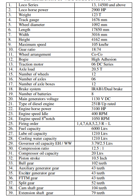
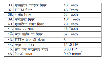
GENERAL DATA OF WDG-3A LOCOMOTIVE
WDG3A Diesel Electric locomotive
W – Broad gauge
D – Diesel Engine
G – Goods Service
3A –Engine Horse Power -3100 HP
This loco is having up rated Diesel engine fitted with fuel efficient kit, Napier or GE make TSC, incorporated IRAB1 and facilitated with AC – DC transmission.
Main compartments of WDG3A Loco from short hood to long hood
1. Nose compartment
2. Loco Pilot cab
3. Control compartment
4. Alternator Room
5. Engine Room
6. Compressor Room
7. Radiator Room
8. Under truck
Short hood – Nose compartment end is called short hood.
Long hood – Radiator room end is called long hood.
Loco Right and Loco left – In loco pilot cab when you stand and facing towards nose compartment, your right hand side is loco right and your left hand side is loco left.
Engine right and engine left – In loco pilot cab when you stand and facing towards engine room, your right hand side is engine right and your left hand side is engine left.
Power take off end – In engine room alternator end is called power take off end.
Free end – In engine room compressor end is called free end.
Note-
1. Counting of parts of Alternator room, Engine room and compressor room as per Engine left and Engine right.
2. Counting of parts of Locomotive parts from short hood to long hood.
3. counting of parts of Engine from free end to power take off end.
Different major parts in compartments
1. Nose Compartment
Dynamic Braking Blower motor ( BKBL) Dynamic braking Grids
NS-1 Reducing valve and its COC Battery knife switch (BS)
Control Reservoir with drain cock Horn and wiper COC
a. On brake panel
MU2B valve, 3/4” COC, C3W distributor valve, F1 selector valve, C2 relay valve, Addl. C2 relay valve, N1 limit valve, D24B valve, 24AD check valve, EPG pressure switch, EPG COC, MR pressure gauge, Power cut off pressure switch, Air flow measuring valve, 1¼” COC, Duplex valve, EPG toggle switch, 110 cubic inch reservoir. On outer wall of Nose compartment head light, flasher light marker light and multiple unit jumper couples are provides.
2. Loco Pilot Cab
a. On both control Desk
A-9 valve with COC SA- 9 valve with COC
Master Handle (MH) Selector Handle (SH)
Reverser Handle (RH) Load meter
Brake pipe Pressure Gauge Air flow indicator
MR pressure Gauge BC pressure gauge
Lighting switches Speedometer
Head light switch (HLS) PATB
Flasher light control box Foot paddle switch
Multiple unit shut down switch (MUSD) Sander push button
Master Fuel pump Breaker (MFPB) Main control breaker MCB
Generator Field cut out switch (GFCO) Indication Lamp panel
Horn push button
Other than above Loco Pilot Cab has Emergency flap valve, Hand Brake, Wiper servo motor, Dom light.
b. On front panel wall
Cab light circuit breaker Head light circuit breaker
Engine room light circuit breaker Dom light circuit breaker
Cyclone motor circuit breaker MB-1
MB-2 FPB
AGFB CEB
Alarm push button ECS
GR1 GR2
Alarm gong MCO
Indication panel Start button
Stop button GFOLR reset button
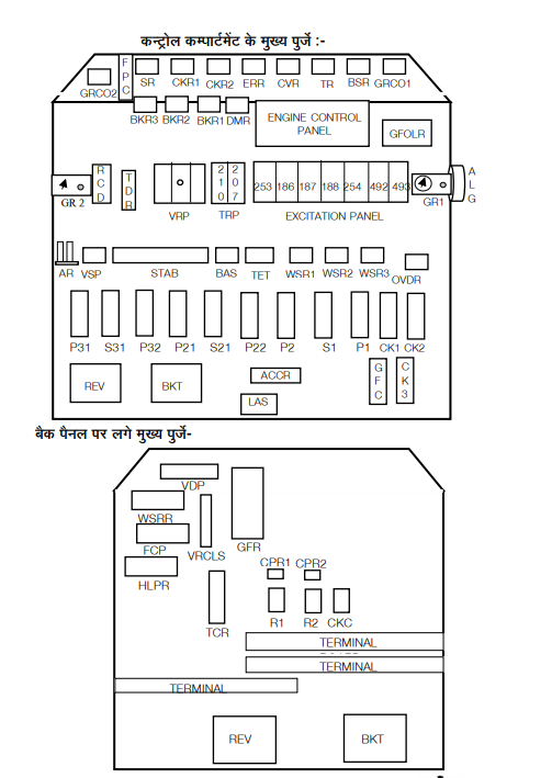
3. Control Compartment
4. Alternator Room
Traction Alternator, Auxiliary Generator,
Exciter Generator, FTTM,
Generator Gear Case and its dip stick gauge, rectifier panel.
5. Engine Room
251-B up rated with fuel efficient kit type diesel engine
Fuel injection pump, High Pressure Line, Water Jumper pipe, Water riser pipe, Inlet elbow, Exhaust elbow, Exhaust manifold, Cross over pipe
On engine right side
Engine Governor, Tacho Generator, Lube oil Dipstick gauge Crankcase Explosion Door , Primary filter, Secondary filter, OSTA Fuel oil Relief valve, Bubble collector, Lube secondary Header, Centrifugal filter, Right side fuel oil gallery
On engine left hand side
Crank case Exhauster Motor& Blower, Fuel oil Regulating valve Lube oil strainer, Bubble collector, Lube oil Main Header Lube secondary Header, Left side fuel oil gallery
On free end
Turbo super charger, After cooler, Water pump ,Lube oil pump
6. Compressor Room
Compressor unit, Cyclonic filter, Fuel pump motor(Fuel pump, Gov. pump), Water drain cock, Car body filter, ETS-1, 2, 3.
Water temperature gauge, LWS& its Test cock, Lube oil relief valve Lube oil regulating valve, EPG’s EP valve and its COC with dirt collector
7. Radiator Room
Lube oil filter drum and its drain cocks Lube oil by pass valve Lube oil cooler Radiator core Radiator fan Rear Truck Traction Motor Blower (RTTM) Expansion tank no. 1&2 Right Angle Gear Box Eddy current clutch coil (ECC) On outer wall of radiator Room Head light flasher light, water level gauge, marker light and multiple unit jumpers are provided.
8. Under Truck
CO-CO high adhesion bogie Front truck
Rear Truck Center Pivot
Side load Bearer Helical Spring
Vertical Shock absorber(08) Horizontal shock absorber (04)
Equalizing beam Axle Box
Compensating beam D shackle (08)
Axle Journal Traction motor
Nose pad Pinion Gear
Axle Gear Traction Motor Gear case
Brake cylinder Brake assembly
Wheels Sanding Arrangement
Rail Guard Cattle Guard
Pipes of Brake System Buffers
Center Buffer coupler Fuel Tank
MR Tank Axle Generator
Mechanical speedometer sensor Hand brake chain
Bogie COC
Front Truck Traction Motor Blower (FTTM)
Location – Alternator room Function – To cool Traction motor no 1, 2 and 3 by air, its shaft having 43 teeth gear which is driven by Main Alternator bull gear. Incase of abnormal sound from FTTM, fail the loco.
Rear Truck Traction Motor Blower (RTTM)
Location- Radiator room Function – To cool Traction motor no 4, 5, and 6 by air. It shaft is having a pulley which has 6 “v” belts, these belts are driven by a pulley on extension shaft No. 2 Minimum 4 belts are required. Engine must be shutdown to check the belts and its tension. If the number of belts is less then 4, fail the loco.